
Calibration module for TIADC system clock mismatch errors and calibration method

A system clock, mismatch error technology, applied in the direction of analog/digital conversion calibration/test, etc., can solve the problem of input signal frequency limitation, unsatisfactory calibration effect, high reference channel requirements, achieve fast calibration rate, good calibration effect, The effect of low computational complexity

Inactive Publication Date: 2016-01-20
HEFEI UNIV OF TECH
View PDF4 Cites 16 Cited by
  • Summary
  • Abstract
  • Description
  • Claims
  • Application Information

AI Technical Summary

Problems solved by technology

The correlation-based algorithms proposed by S.Jamal and D.Fu et al. (A10-b120-Msample / stime-interleavedanalog-to-digitalconverterwithdigitalbackgroundcalibration) to calibrate the clock mismatch error, however, this scheme is only applicable to two The TIADC of one channel cannot be extended to more channels or even any channel
Chung-YiWang and Jieh-TsorngWu et al proposed to do zero detection between channels to extract the clock mismatch error between channels (“ABackgroundTiming-SkewCalibrationTechniqueforTime-InterleavedAnalog-to-DigitalConverters” Chung-YiWang, StudentMember, IEEE, and Jieh-TsorngWu ,Member,IEEE), however, this scheme has limitations on the frequency of the input signal, and the calibration effect is not ideal in the case of high frequency
RogerPetigny and HugoGicquel et al. proposed to add a reference channel with similar accuracy to the TIADC sub-channel for calibration ("BackgroundTimeSkewCalibrationforTime-InterleavedADCUsingPhaseDetectionMethod"). However, this solution has relatively high requirements for the reference channel and high hardware consumption.
ArashShahmansoori et al. proposed to use DTFT filtering to calibrate the clock mismatch error ("Consecutive adaptive blind estimation of timing offsets for arbitrary channel time-interleaved ADCs"), but this solution can only calibrate the clock mismatch error of each channel sequentially, and the calibration rate is low

Method used


Image

  • Calibration module for TIADC system clock mismatch errors and calibration method
  • Calibration module for TIADC system clock mismatch errors and calibration method
  • Calibration module for TIADC system clock mismatch errors and calibration method

Examples


Embodiment Construction

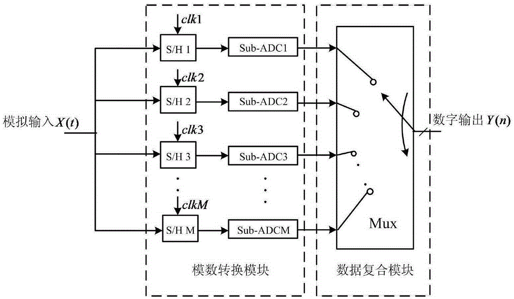
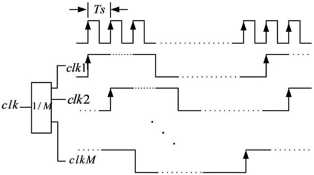
[0093] In this embodiment, a TIADC system in a calibration module for TIADC system clock mismatch error is composed of an analog-to-digital conversion module and a data composite module, such as Figure 1a As shown, wherein, the analog-to-digital conversion module is composed of M sampling and holding circuits and M sub-channel ADCs; the M sampling and holding circuits are respectively controlled by M sampling clock signals; as Figure 1b As shown, M sampling clock signals are obtained by frequency division of the sampling clock clk of the TIADC system through a frequency divider; the sampling clock period of a single sub-channel ADC is M times the sampling clock period of the TIADC system;

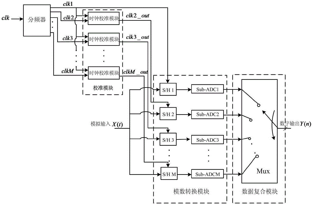
[0094] The sampling clock signal clk1 of the first sub-channel ADC is used as the reference clock signal, and the sampling clock signals of the remaining M-1 sub-channel ADCs are calibrated, and the M-1 sampling clock signals except the first sub-channel ADC, that is, in A clock calibratio...


PUM


Abstract

The invention discloses a calibration module for TIADC system clock mismatch errors and a calibration method. The invention is characterized in that the calibration module comprises a delay module, a subtractor module, a clock sampling module, an error judgment module and a variable delay line module; a sampling clock signal of a first sub channel ADC as a reference clock signal, a clock calibration module is disposed between a sampling clock signal of each of other M-1 sub channel ADC and the corresponding sampling hold circuit of each of the M-1 sub channel ADC; and in this way, the M-1 clock calibration modules constitute the calibration module. The invention is suitable for calibration of a TIADC system of any number of channels and for signals in the entire Nyquist sampling frequency, can be used for easily obtaining the clock mismatch errors of each channel and performing efficient compensation, and therefore achieve the calibration of TIADC clock mismatch errors quickly and accurately with less hardware spending.

Description

technical field [0001] The invention relates to the field of analog-to-digital conversion, in particular to a multi-channel time-interleaved analog-to-digital converter clock mismatch error calibration module and a calibration method thereof. Background technique [0002] With the wide application of digital signal processing technology in medical equipment, communication, consumer electronics and other fields, the analog-to-digital converter as a bridge between the analog world and the digital world is particularly important. However, with the development of deep submicron CMOS technology towards lower power supply voltage and smaller feature size, the design of high-precision, high-speed analog-to-digital converters using traditional structures will become more and more difficult. [0003] The multi-channel time-interleaved ADC can break through the limitation brought by process factors through parallel acquisition technology, so that the speed of the analog-to-digital con...

Claims


Application Information

Patent Timeline
Patent Type & Authority Applications(China)
IPC IPC(8): H03M1/10
Inventor 尹勇生蹇茂琛陈红梅邓红辉
Owner HEFEI UNIV OF TECH
Learn More