Case structure of portable electronic device

Active Publication Date: 2006-12-14
ASUSTEK COMPUTER INC
View PDF5 Cites 10 Cited by
  • Summary
  • Abstract
  • Description
  • Claims
  • Application Information

AI Technical Summary

Benefits of technology

[0017] In accordance with the embodiments of the present invention, the plug portion driven by the second spring element is utilized for filling the through-hole (such as the first penetrating opening) set on the case structure of a portable electronic

Problems solved by technology

However, the spring element of the hinge 103 sustaining the twist stress in operation is vul

Method used


Image

  • Case structure of portable electronic device
  • Case structure of portable electronic device
  • Case structure of portable electronic device

Examples


Embodiment Construction

[0023] The objective of the present invention is to provide a case structure for an electronic product. The aspects, objectives, features, and many of the attendant advantages of this invention will become more readily appreciated by reference to the following detailed description. The preferred embodiments are provided hereafter, and the portable electronic product may refer to a notebook computer.

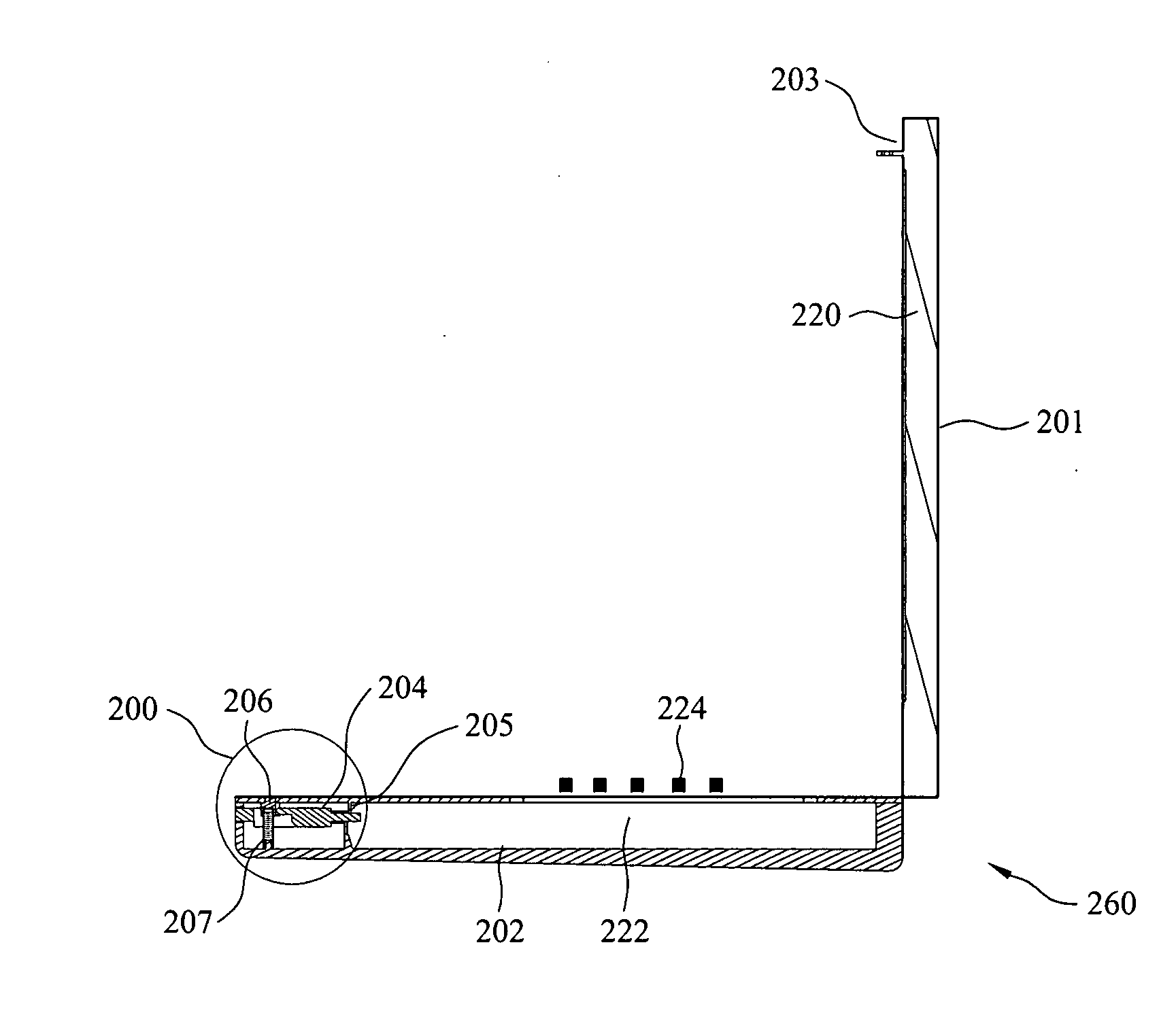
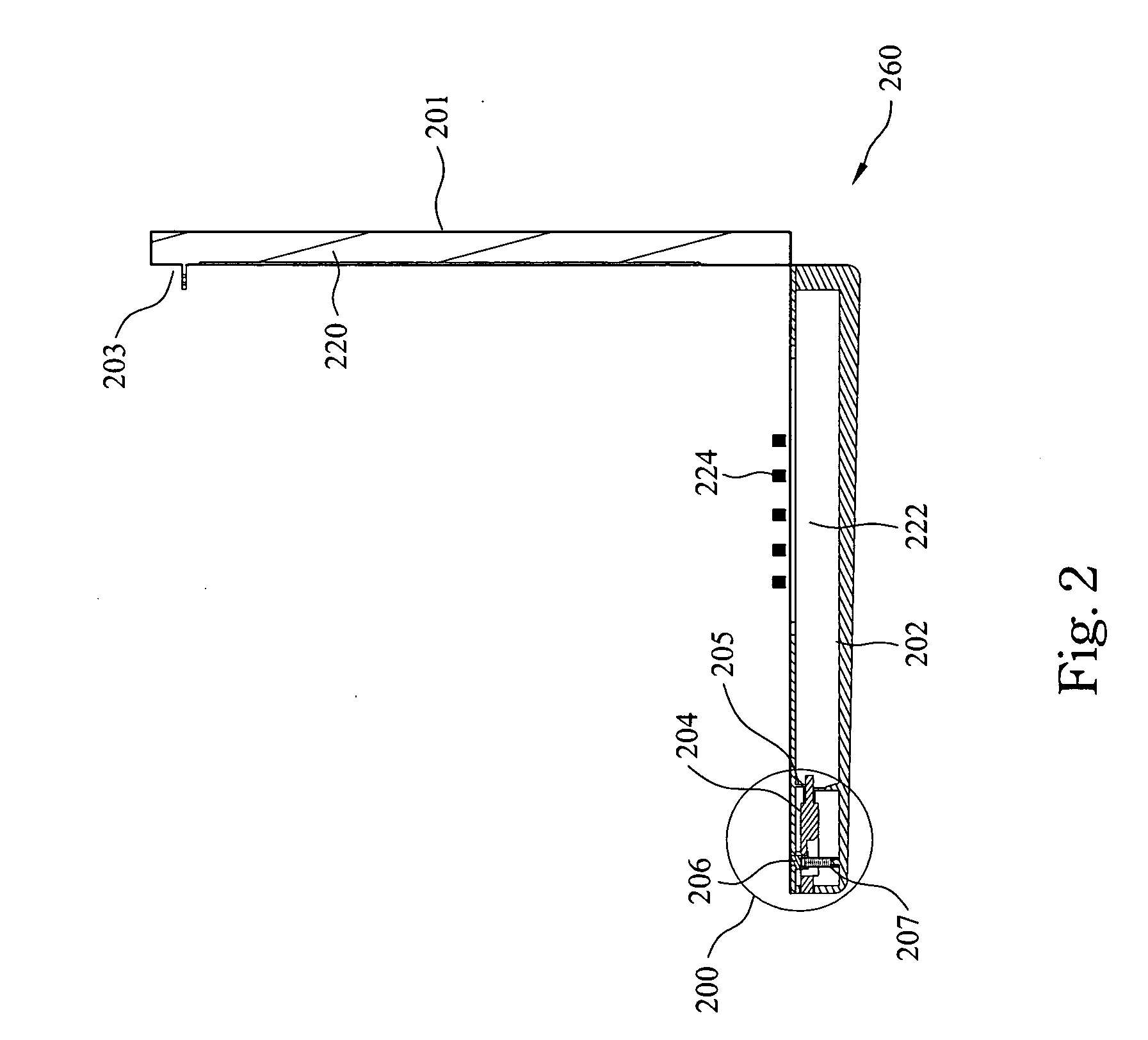
[0024]FIG. 2 illustrates a cross-sectional view of a notebook computer in accordance with a preferred embodiment of the present invention. In the preferred embodiment of the present invention, the notebook computer comprises a case structure 200, a display 220, a main frame 222 and a keyboard 224. The case structure 200 comprises a first shell 201, a second shell 202, a fist engagement element 203, a second engagement element 204, a first spring element 205, a plug element 206 and a second spring element 207. The display 220, the main frame 222 and the keyboard 224 are electrically conne...


PUM


Abstract

A case structure of an electronic device comprises a first shell, a second shell, a first engagement element, a second engagement element, a first spring element, a second spring element and a plug element. The first engagement element protrudes from the first shell. The second shell having a first penetrating opening allows the first engagement element to pass through. The second engagement element having a button portion passes through a second penetrating opening of the second shell. The second engagement element is driven by the button portion and the first spring element to control the second engagement element and the first engagement element to engage or disengage from each other. The plug element located in the second shell is pushed for filling in the first penetrating opening by the second spring element.

Description

RELATED APPLICATIONS [0001] The present application is based on, and claims priority from, Taiwan Application Serial Number 94119524, filed Jun. 13, 2005, the disclosure of which is hereby incorporated by reference herein in its entirety. FIELD OF THE INVENTION [0002] The present invention relates to an electronic product, and more particularly, to a case structure of a portable electronic device. BACKGROUND OF THE INVENTION [0003] Smallness, portability, and convenience are the main trends in a portable electronic device design, such as electronic products like notebook computers, portable TVs, cell phones, or personal digital assistants (PDA). [0004]FIG. 1 is a diagram illustrating a notebook computer in accordance with a prior art. [0005] Traditionally, the case structure of a notebook computer, for example, the main parts of the notebook include a bottom case 102 which consists of the main frame of the notebook and a keyboard are sustained, and a cover case 104 with a display pa...

Claims


Application Information

Patent Timeline
IPC IPC(8): G06F1/16
CPCG06F1/1679G06F1/1616Y10T292/0956Y10T292/0952
Inventor WANG, WEN-HUNG
Owner ASUSTEK COMPUTER INC
Why Eureka
Try Eureka