Relay system and method for cellular communication

Active Publication Date: 2006-12-14
SAMSUNG ELECTRONICS CO LTD
View PDF7 Cites 116 Cited by
  • Summary
  • Abstract
  • Description
  • Claims
  • Application Information

AI Technical Summary

Benefits of technology

[0009] It is, therefore, an object of the present invention to provide a relay system and method for cellula

Problems solved by technology

Up to the present, however, there has been proposed no sp

Method used


Image

  • Relay system and method for cellular communication
  • Relay system and method for cellular communication
  • Relay system and method for cellular communication

Examples


Example

[0020] With reference to the accompanying drawings, a description will now be made of a relay system and method for cellular communication according to the present invention. Descriptions of well-known functions and constructions are omitted for the sake of clarity and conciseness.

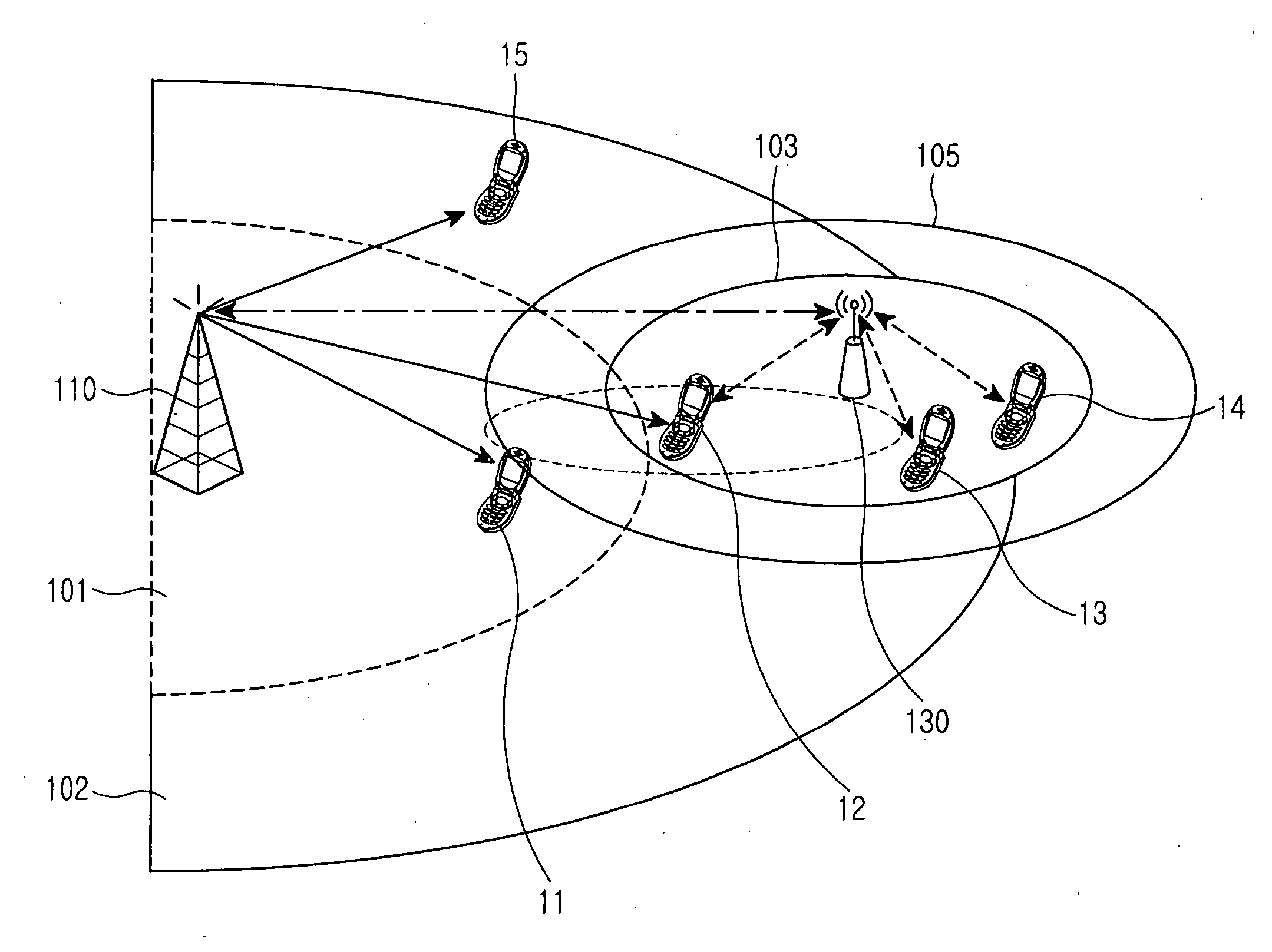
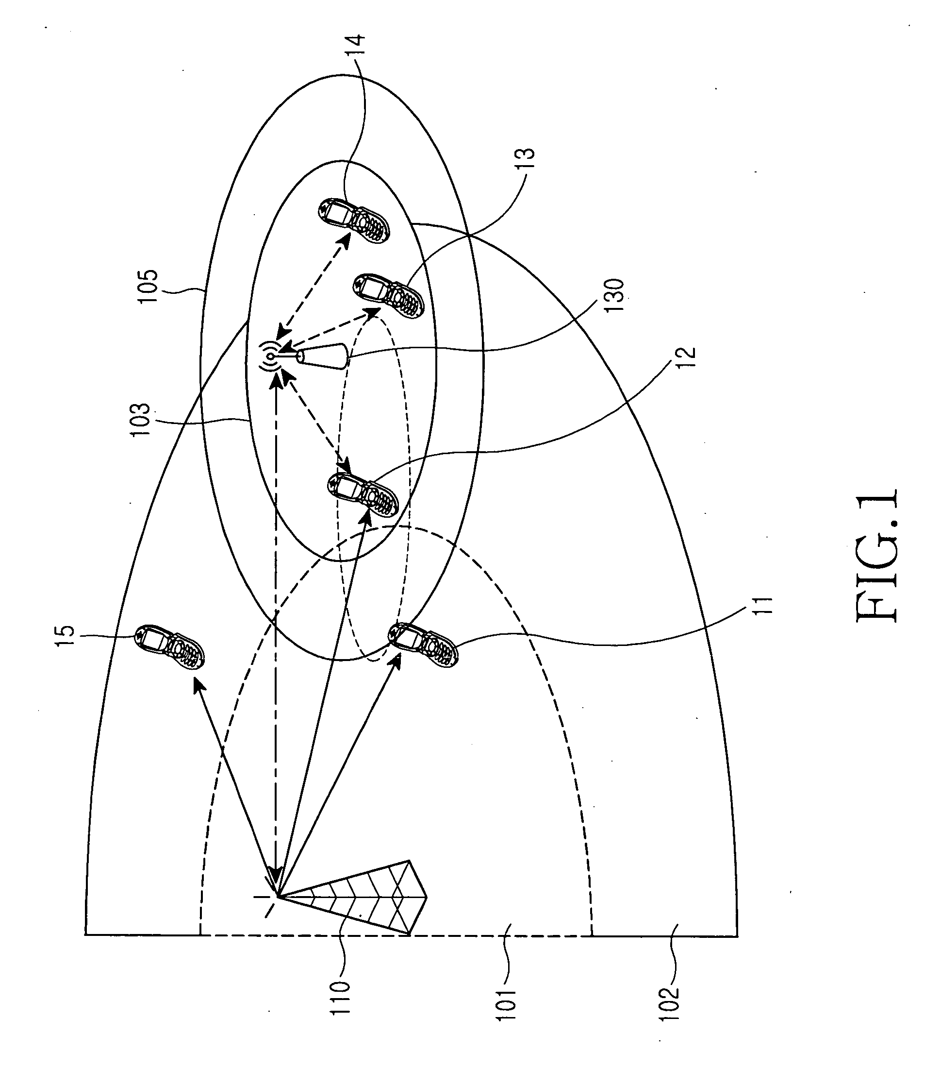
[0021]FIG. 1 is a diagram illustrating architecture of a relay system according to the present invention. In FIG. 1, a service area of a base station 110 that performs communication based on a licensed band (LB) is divided into a first LB service area 101 for low-rate mobility and high-rate data transmission service and a second LB service area 102 for high-rate mobility and low-rate data transmission service. The first LB service area 101 and the second LB service area 102 form their own concentric circles, centering about the base station 110, and the first LB service area 101 has a smaller radius than that of the second LB service area 102.

[0022] At least one relay station 130 is arranged in a boundar...


PUM


Abstract

A relay method is disclosed in a cellular communication system including an access node for providing an access service using resources of a licensed band to a particular terminal among a plurality of terminals with a partial licensed band of the full frequency spectrum, and a relay station for relaying communication between the terminal and an access node. The relay method includes performing base station-led resource allocation on a licensed band for a terminal and a relay station located in a service area of the base station, and performing relay station-led resource allocation on the licensed band and an unlicensed band for a terminal located in a service area of the relay station.

Description

PRIORITY [0001] This application claims the benefit under 35 U.S.C. §119(a) of an application entitled “Relay System and Method for Cellular Communication” filed in the Korean Intellectual Property Office on Jun. 13, 2005 and assigned Serial No. 2005-50472, the contents of which are incorporated herein by reference. BACKGROUND OF THE INVENTION [0002] 1. Field of the Invention [0003] The present invention relates generally to wireless communication, and in particular, to a relay system and method capable of extending a service area and increasing service capacity of a licensed band (LB) system using unlicensed band (UB) resources. [0004] 2. Description of the Related Art [0005] The development and commercialization of various wireless communication technologies requires new frequency bands that do not overlap licensed bands for the existing wireless communication technology, due to the characteristics of wireless communication based on the limited frequency resources. However, almost...

Claims


Application Information

Patent Timeline
IPC IPC(8): H04B7/15H04W16/26
CPCH04W16/26H04B7/2606H04W84/047H04B7/15
Inventor LEE, YEON-WOOYUN, SANG-BOH
Owner SAMSUNG ELECTRONICS CO LTD
Why Eureka
Try Eureka