Sub-access point, system, and method for adjusting power of transmission signal

a technology of transmission signal and sub-access point, which is applied in the field of sub-access point, system and method for adjusting the power of transmission signal, can solve the problems of home or the predetermined region not being able to service by using a single ap, data transfer rate may be considerably lower, and communication may not be successful, so as to achieve the effect of eliminating shadow areas

Active Publication Date: 2006-04-20
SAMSUNG ELECTRONICS CO LTD
View PDF5 Cites 26 Cited by
  • Summary
  • Abstract
  • Description
  • Claims
  • Application Information

AI Technical Summary

Benefits of technology

[0018] The present invention provides a sub-access point (AP), and a system and method for adjusting the power of a transmission signal which can eliminate shadow areas by adjusting the power of a transmission signal output from the sub-AP based on received signal strength indicator (RSSI) readings and frame error rate (FER) of a main AP.

Problems solved by technology

In some cases, however, the home or the predetermined region cannot be serviced by using a single AP because of the building structure or topography—a problem which will be described in detail below with reference to FIG. 1.
However, a room adjacent to the living room and shielded by walls may get only a weak signal, if any, transmitted by the AP installed in the living room.
Thus, in this adjacent room the data transfer rate may be considerably lower, or communication may be unsuccessful.
However, since in a room other than the living room it is difficult to receive a signal transmitted by the AP, portions of the room are rendered in lighter shading to represent the low RSSI.
Accordingly, a Voice over Internet Protocol (VoIP) service cannot be provided to such a shadow area.
In this case, however, if the two APs use the same channel, they may interfere with each other, thereby deteriorating the performance of the wireless network.
In this situation, however, the entire network capacity decreases especially in a densely populated place, such as an apartment building, because of a shortage of available channels.
In this patented method, however, even when the transmission power levels of the stations in the wireless LAN are successfully controlled, it is still very difficult to completely eliminate shadow areas simply by using a single AP.

Method used


Image

  • Sub-access point, system, and method for adjusting power of transmission signal
  • Sub-access point, system, and method for adjusting power of transmission signal
  • Sub-access point, system, and method for adjusting power of transmission signal

Examples


Embodiment Construction

[0030] Advantages and features of the present invention and methods of accomplishing the same may be understood more readily by reference to the following detailed description of illustrative, non-limiting embodiments and the accompanying drawings. The present invention may, however, be embodied in many different forms and should not be construed as being limited to the embodiments set forth herein. Rather, these exemplary embodiments are provided so that this disclosure will be thorough, complete, and will fully convey the concept of the present invention to those skilled in the art, and the present invention will only be defined by the appended claims. Like reference numerals refer to like elements throughout the specification.

[0031] The present invention will now be described more fully with reference to the accompanying drawings, in which illustrative, non-limiting embodiments of the invention are shown.

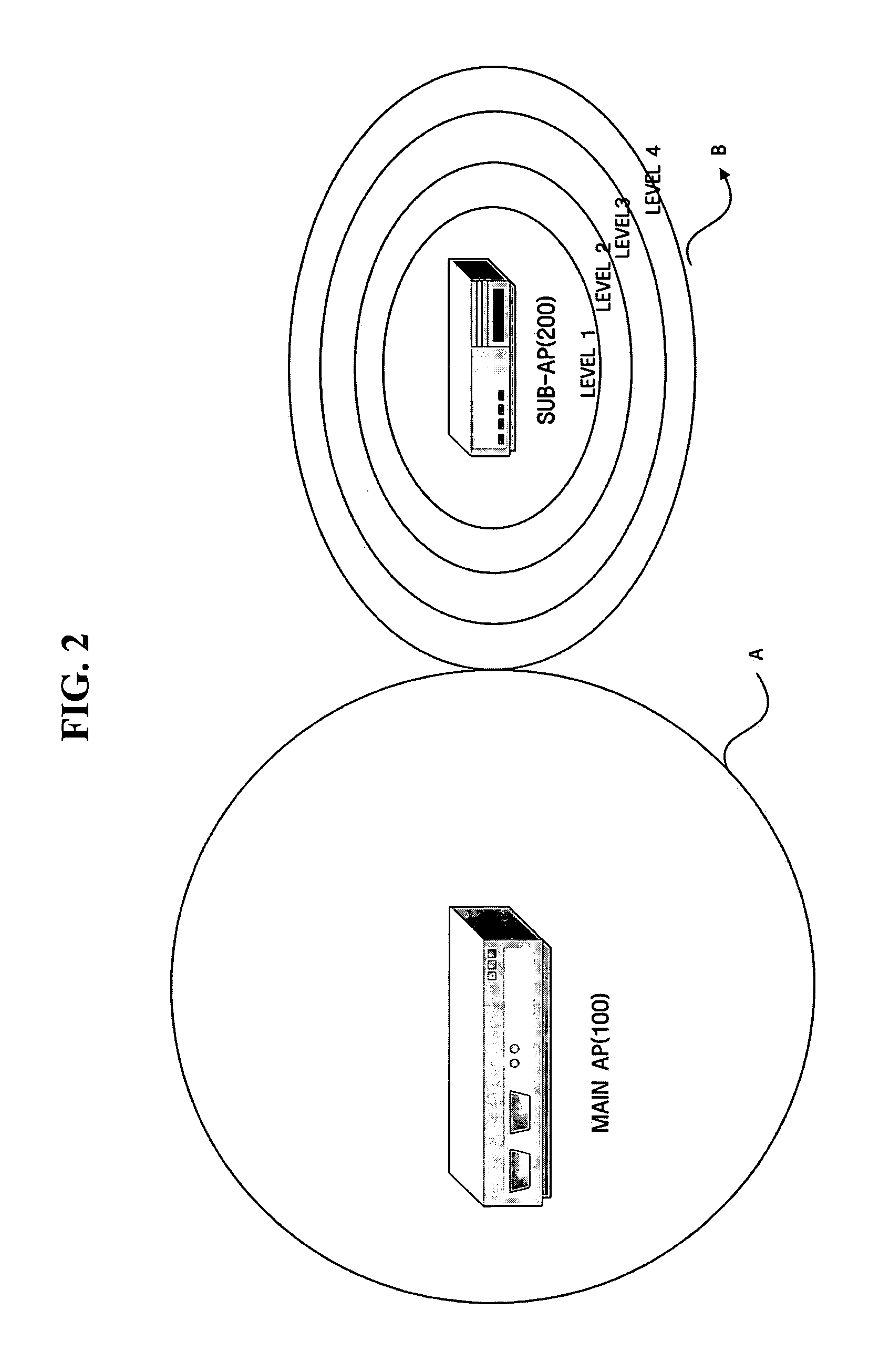
[0032]FIG. 2 is a schematic diagram of a system for adjusting the power of...


PUM


Abstract

A sub-access point (AP), system, and method for adjusting a power level of a transmission signal, and more particularly, in which the power level of a transmission signal output from the sub-AP is adjusted based on received signal strength indicator (RSSI) readings and frame error rate (FER) of a main AP, thereby eliminating shadow areas and minimizing interference between the main AP and the sub-AP. The sub-AP includes a reception unit which receives a beacon frame and a data frame from a main AP, a RSSI checking unit which checks an RSSI of the main AP, a FER checking unit which checks an FER, and a control unit which determines a power level at which a transmission signal is to be transmitted based on the identified RSSI and the identified FER and causes a transmission signal to be output at the determined power level.

Description

CROSS-REFERENCE TO RELATED APPLICATION [0001] This application claims priority from Korean Patent Application No. 10-2004-0083589 filed on Oct. 19, 2004 in the Korean Intellectual Property Office, the disclosure of which is incorporated herein by reference in its entirety. BACKGROUND OF THE INVENTION [0002] 1. Field of the Invention [0003] The present invention relates to a sub-access point (AP), system, and method for adjusting the power of a transmission signal, and more particularly, to a sub-AP system and method for adjusting the power of a transmission signal, in which the power of a transmission signal output from the sub-AP is adjusted based on received signal strength indicator (RSSI) readings and a frame error rate (FER) of a main AP, thereby eliminating shadow areas and minimizing the interference between the main AP and the sub-AP. [0004] 2. Description of the Related Art [0005] In general, in a wireless local area network (LAN), a home or a predetermined region can be se...

Claims


Application Information

Patent Timeline
Patent Type & Authority Applications(United States)
IPC IPC(8): H04Q7/24
CPCH04B17/318H04W16/26H04W52/143H04W52/20H04W52/24H04W84/12H04W88/08
Inventor MIN, IN-HONG
Owner SAMSUNG ELECTRONICS CO LTD
Why Eureka
Try Eureka