Sanitary napkin
a technology of sanitary napkin and absorbent member, which is applied in the field of sanitary napkin, can solve the problems of difficult to bring the absorbent member, intergluteal cleft without fail, etc., and achieve the effects of eliminating the fear of rearward leakage of menstrual blood, convenient positioning, and easy conta
- Summary
- Abstract
- Description
- Claims
- Application Information
AI Technical Summary
Benefits of technology
Problems solved by technology
Method used
Image

Examples
first embodiment
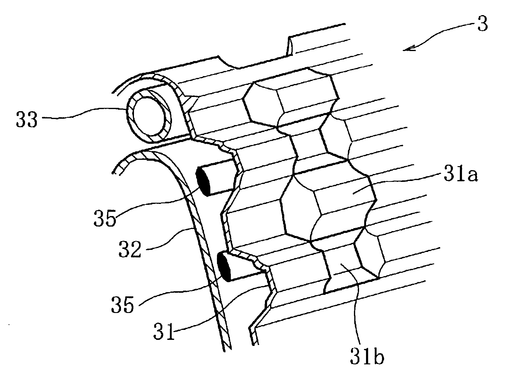
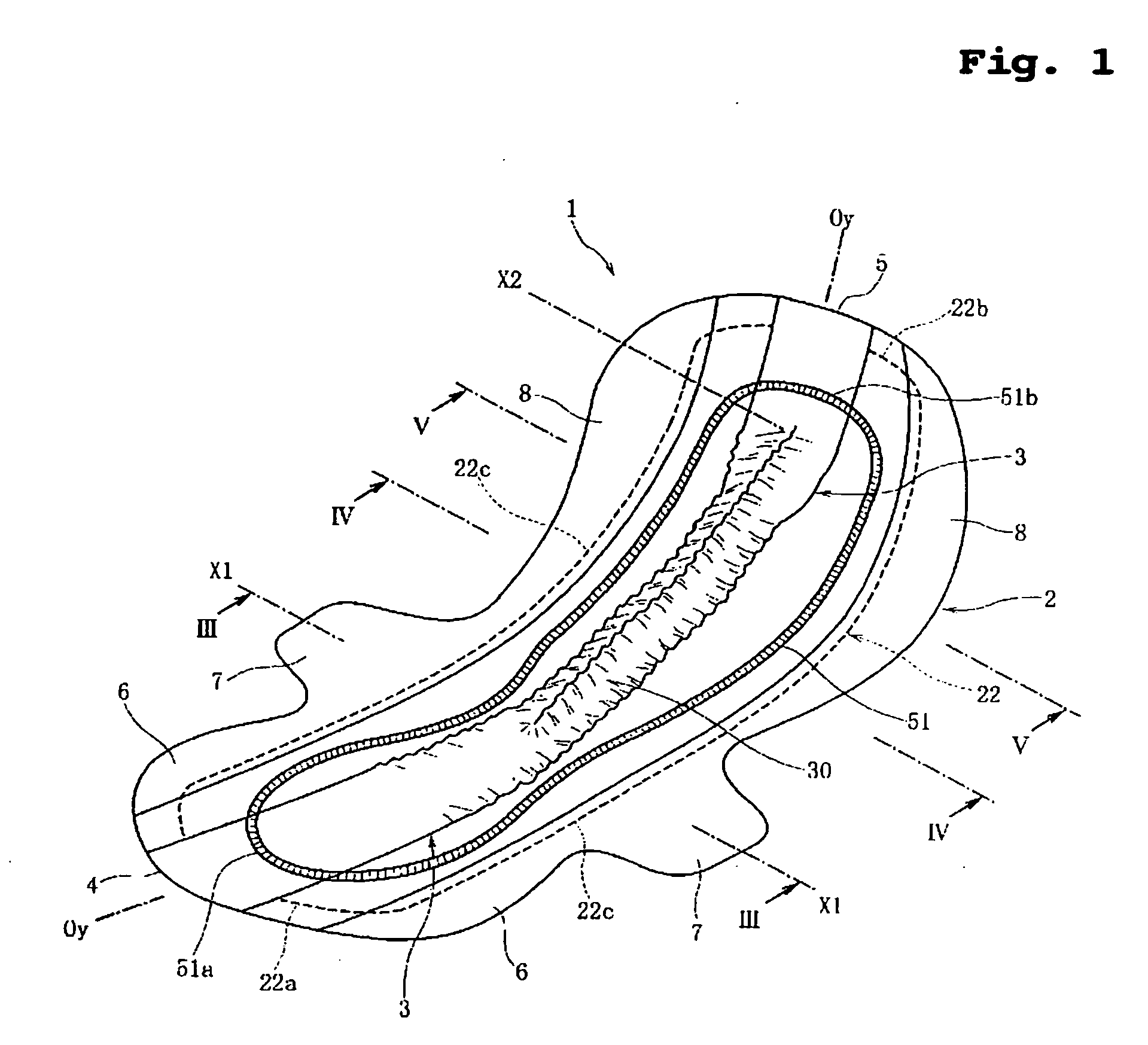
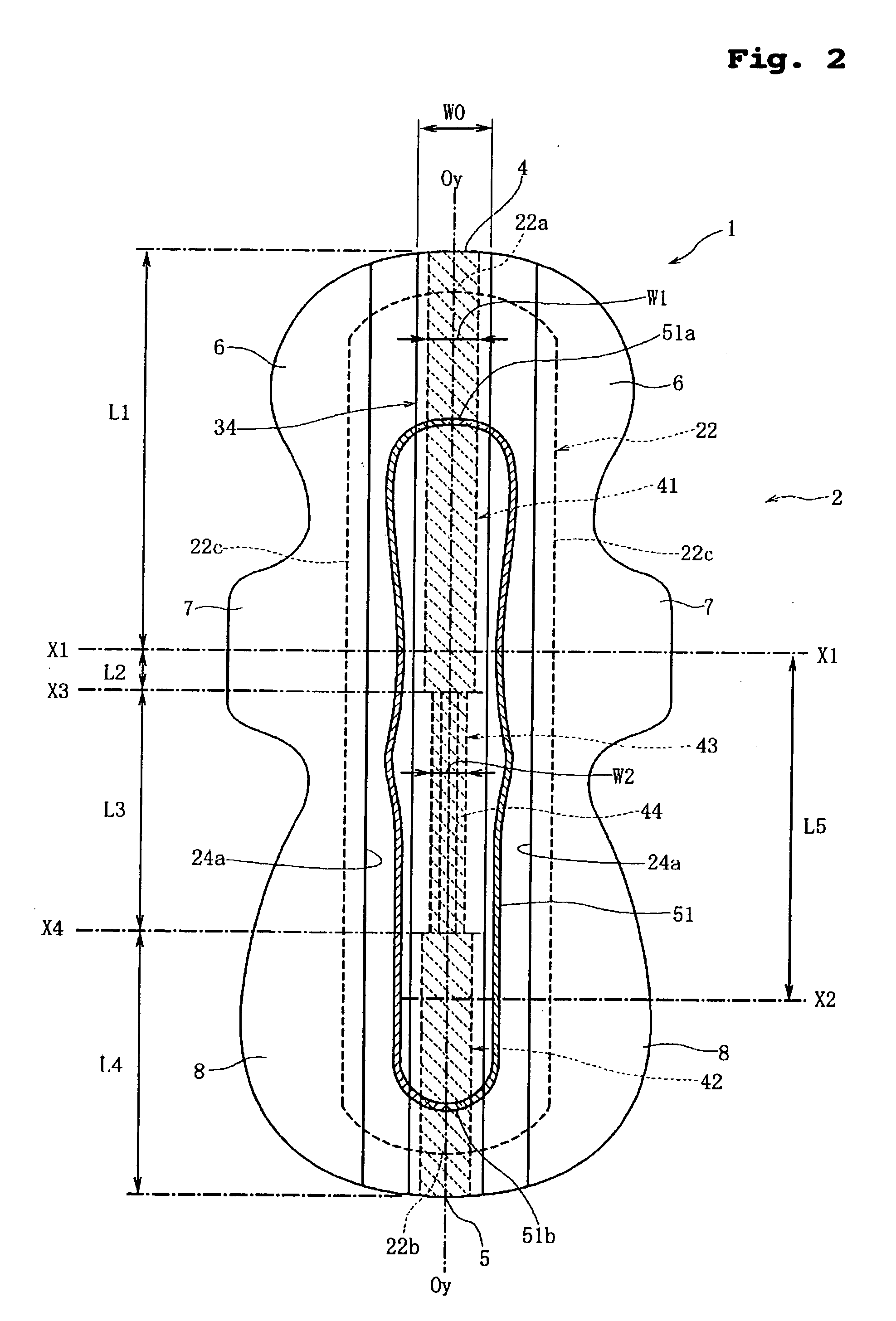
[0053]FIG. 1 is a perspective view of a sanitary napkin according to the present invention in a state where no external force is exerted thereon. FIG. 2 is a plan view of the sanitary napkin in a flattened state, showing how a connection sheet is fixed to a main body. FIG. 3 is a sectional view taken along line III-III of FIG. 1, FIG. 4 is a sectional view taken along line IV-IV of FIG. 1, and FIG. 5 is a sectional view taken along line V-V of FIG. 1. FIG. 6 is a sectioned perspective view for more detailed description of the section taken along the line IV-IV of FIG. 1. FIG. 7 is an enlarged sectioned perspective view showing a part of a projection on an enlarged scale. FIG. 8(A) is a side view of the sanitary napkin in a state where no external force is exerted thereon, and FIG. 8(B) is a side view of the sanitary napkin in a state where a part of the projection is separated from the main body. FIG. 9(A) is an enlarged plan view showing means for temporarily fixing the connection ...
second embodiment
[0118]FIG. 13 is a sectional view taken in the temporarily fixing region 43 as in FIG. 4, showing a sanitary napkin 101 according to the present invention.
[0119] The sanitary napkin 101 differs from the sanitary napkin 1 of the first embodiment in that the sanitary napkin 101 has a topsheet 123 which is liquid-permeable and disposed to cover not only the body surface of the liquid-absorbent layer 22 of the main body 2 but also the tubular laminated sheet 30. In the temporarily fixing region 43, the connection sheet 34 is separably fixed to the body surface of the liquid-absorbent layer 22; in the front and rear firmly fixing regions 41, 42, the connection sheet 34 is firmly fixed to the body surface of the liquid-absorbent layer 22. Here it is preferred that the liquid-absorbent layer 22 is formed by wrapping pulp in a hydrophilic paper or nonwoven fabric and the connection sheet 34 is separably or firmly fixed to the hydrophilic paper or nonwoven fabric. In the sanitary napkin 101,...
third embodiment
[0121]FIG. 14 is a sectional view taken in the temporarily fixing region 43 as in FIGS. 4 and 13, showing a sanitary napkin 201 according to the present invention.
[0122] The projection 3 is formed of a liquid-permeable interior sheet 232 and a liquid-permeable exterior sheet 231 covering the interior sheet 232. The exterior sheet 231 is bonded at its central portion to the interior sheet 232 through a hot-melt type adhesive and at its side portions to the body surface of the liquid-absorbent layer 22 of the main body 2.
[0123] In the temporarily fixing region 43, the interior sheet 232 and the exterior sheet 231 have cuts 244 at lower parts of the side walls of the projection 3. The cuts 244 are arranged at spaced intervals in the longitudinal direction in the form of perforation. In the front and rear firmly fixing regions 41, 42, on the other hand, the projection 3 does not have the cuts 244. In the third embodiment, the cuts 244 function as the temporarily fixing means.
[0124] In...
PUM
 Abstract
Description
Claims
Application Information
 - R&D
- Intellectual Property
- Life Sciences
- Materials
- Tech Scout
- Unparalleled Data Quality
- Higher Quality Content
- 60% Fewer Hallucinations
Browse by: Latest US Patents, China's latest patents, Technical Efficacy Thesaurus, Application Domain, Technology Topic, Popular Technical Reports.
© 2025 PatSnap. All rights reserved.Legal|Privacy policy|Modern Slavery Act Transparency Statement|Sitemap|About US| Contact US: help@patsnap.com