Eureka AIR delivers breakthrough ideas for toughest innovation challenges, trusted by R&D personnel around the world.

Methods and apparatus for modeling gas turbine engines

Inactive Publication Date: 2006-12-14
GENERAL ELECTRIC CO
View PDF21 Cites 4 Cited by
  • Summary
  • Abstract
  • Description
  • Claims
  • Application Information

AI Technical Summary

Benefits of technology

[0006] In another aspect of the invention, a modeling system is provided for use in modeling a gas turbine engine that includes a pulse detonation system. The modeling system includes a computer including a processor, and at least one database that is coupled to the comput

Problems solved by technology

However, such methods only model the pulse detonation system, and may not obtain additional data regarding operating conditions within the system for a plurality of flight conditions.

Method used


Image

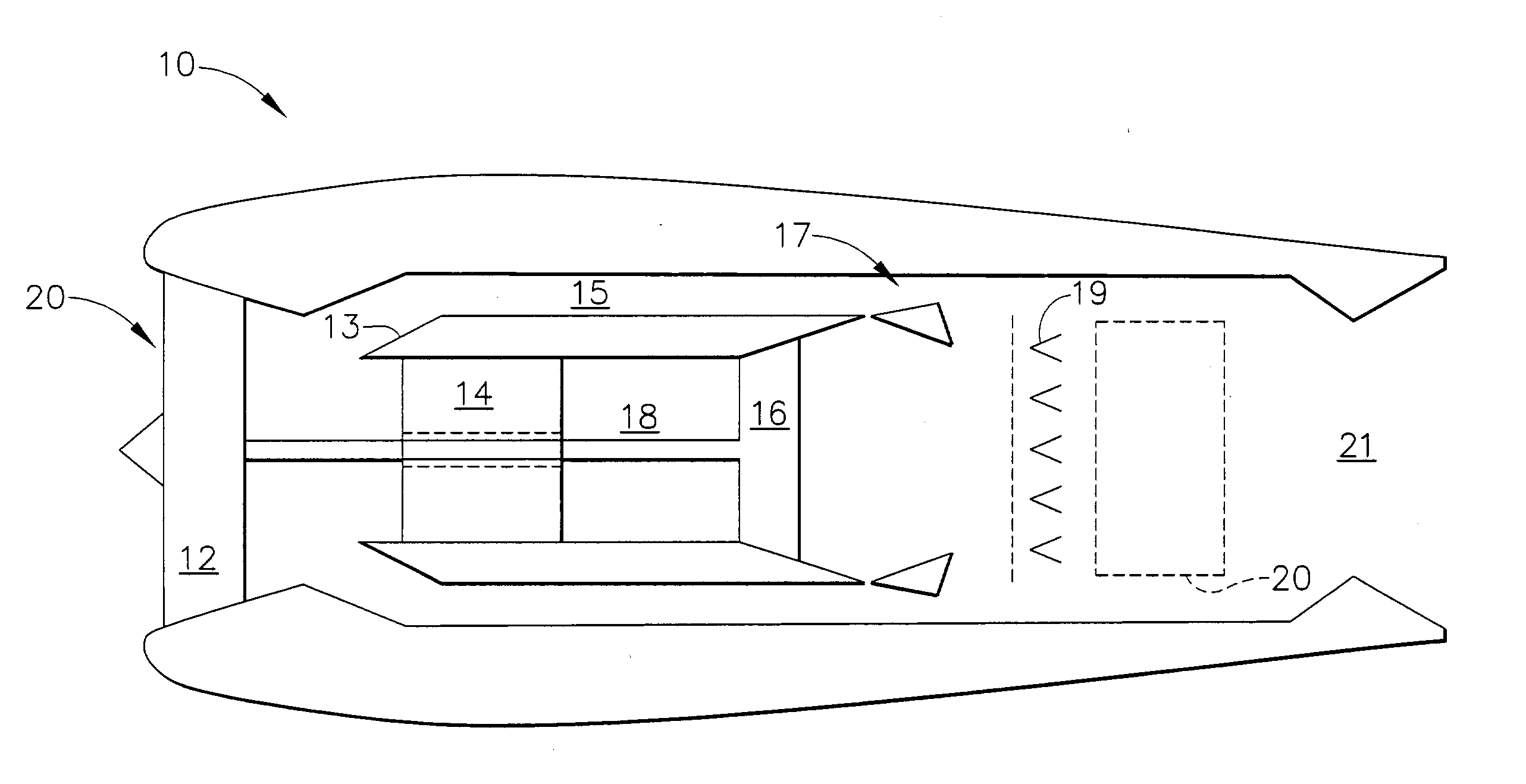
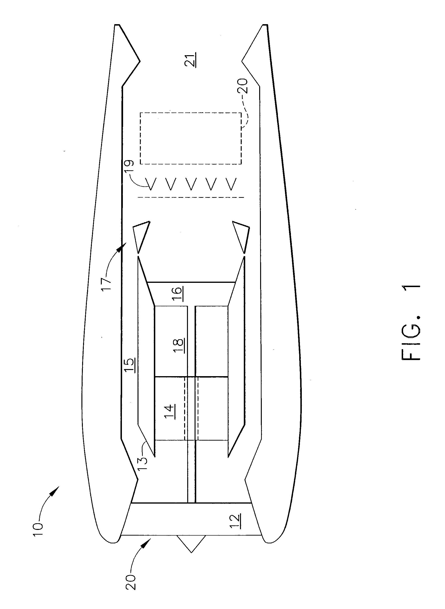
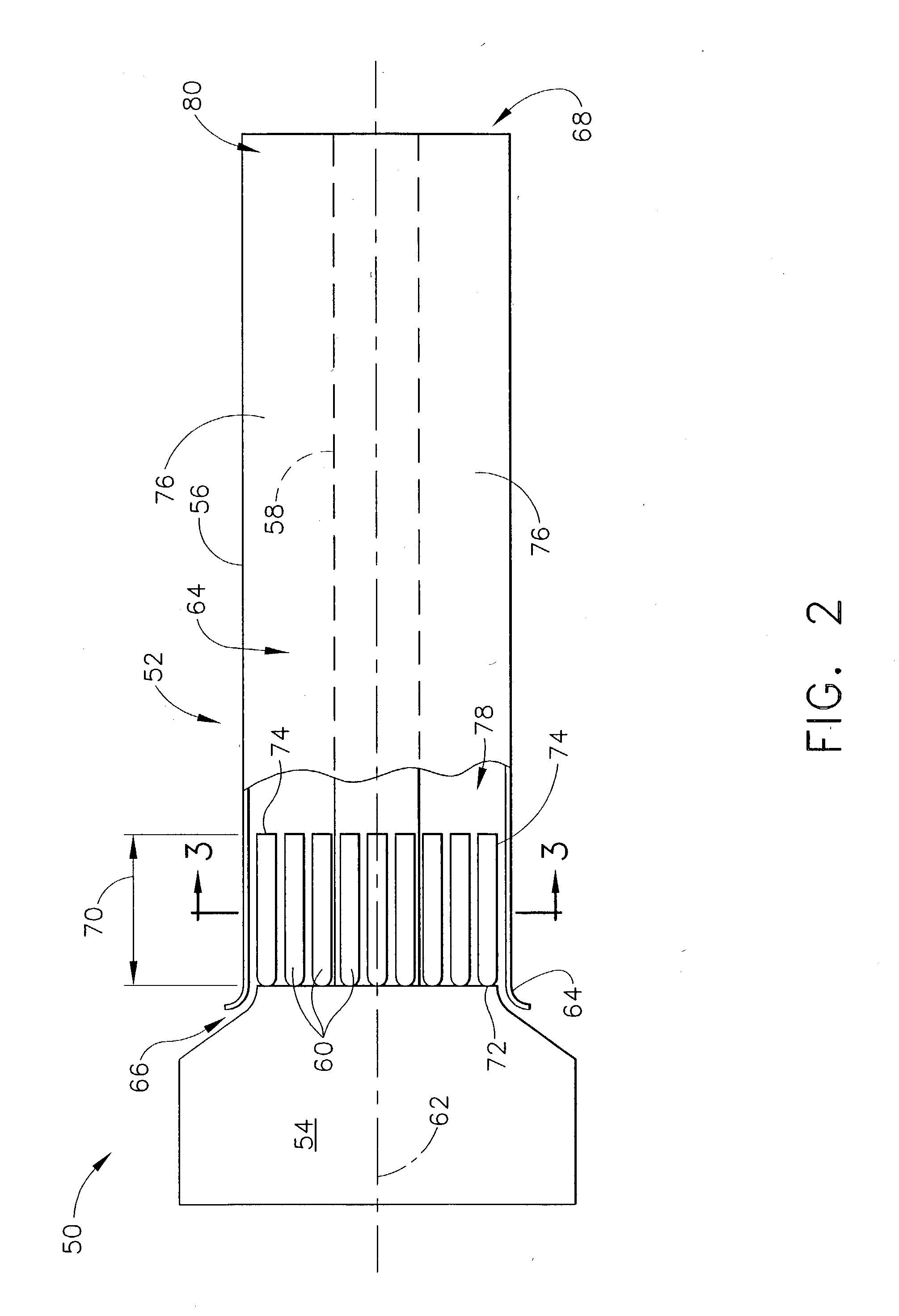
  • Methods and apparatus for modeling gas turbine engines
  • Methods and apparatus for modeling gas turbine engines
  • Methods and apparatus for modeling gas turbine engines

Examples


Embodiment Construction

[0014] As used herein, the term “design characteristics” may include any characteristic or specification used in defining the design of a pulse detonation system or gas turbine engine. For example, “design characteristics” may include the geometry of a component within a pulse detonation system or gas turbine engine, or the size, weight, or strength of a pulse detonation system component, a gas turbine engine component, a pulse detonation system generally, or a gas turbine engine generally. The above examples are exemplary only, and are thus not intended to limit in any way the definition and / or meaning of the term “design characteristics”. As used herein, the term “performance characteristics” may include anything defining the performance of a pulse detonation system or gas turbine engine. For example, “performance characteristics” may include the thrust to weight ratio of a pulse detonation system or a gas turbine engine. The above example is exemplary only, and is thus not intend...


PUM


Abstract

A method enables modeling of a gas turbine engine that includes a pulse detonation system. The method includes providing a pulse detonation modeling system, predicting characteristics of the engine using the pulse detonation modeling system, and predicting characteristics of the pulse detonation system using the pulse detonation modeling system.

Description

BACKGROUND OF THE INVENTION [0001] This invention relates generally to gas turbine engines and more specifically, to a method and apparatus for modeling a gas turbine engine that includes a pulse detonation system. [0002] At least some known pulse detonation systems use a series of repetitive detonations within a detonation chamber to produce a high pressure exhaust. More specifically, a fuel and air mixture is periodically detonated within a plurality of tubes, or other geometric configurations, such as an annular chamber, positioned within the detonation chamber to cause a strong shock wave to propagate at supersonic speeds through the unburned fuel-air mixture. The passage of the strong shock wave causes a mode of combustion, known as detonation, to occur behind, and closely coupled to, the strong shock wave, a condition herein referred to as the detonation wave or the detonation front. More specifically, the detonation wave increases the temperature and pressure within the combu...

Claims


Application Information

Patent Timeline
IPC IPC(8): G06G7/48F02K3/04F02C7/00F02K3/08F02K7/02F02K7/04F23R7/00G06F17/50
CPCF02K3/04Y02T50/671F02K7/02F02K3/08
Inventor PARSONS, FRANKLIN D.MOYNIHAN, THOMAS M.VENKATARAMANI, KATTALAICHERI S.
Owner GENERAL ELECTRIC CO
Why Eureka
Eureka Blog
Learn More