Pressure-assisted toilet flush cartridge

Inactive Publication Date: 2006-12-21
WATER CONTROL TECH CORP
View PDF5 Cites 4 Cited by
  • Summary
  • Abstract
  • Description
  • Claims
  • Application Information

AI Technical Summary

Benefits of technology

[0008] A further embodiment includes method of reducing noise in a pressure assisted toilet that in

Problems solved by technology

A disadvantage of the prior art pressure assisted toilet system is that the noise generated during flushing has restricted its use in residential applications where excessive noise is undesirable.
This noi

Method used


Image

  • Pressure-assisted toilet flush cartridge
  • Pressure-assisted toilet flush cartridge
  • Pressure-assisted toilet flush cartridge

Examples


Embodiment Construction

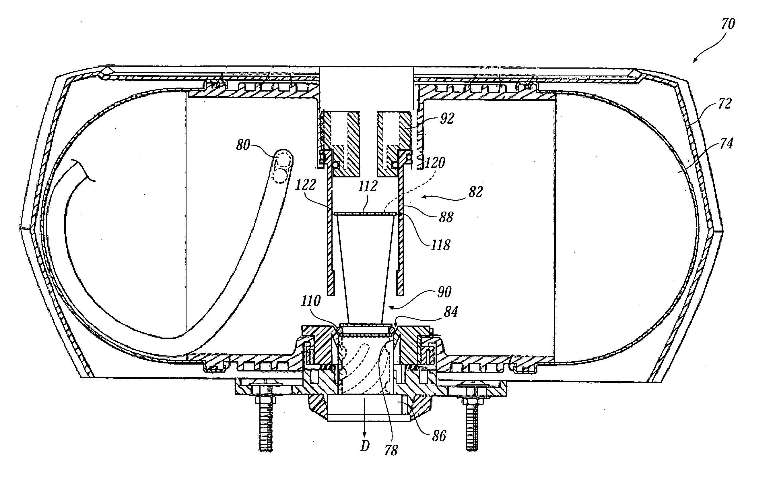
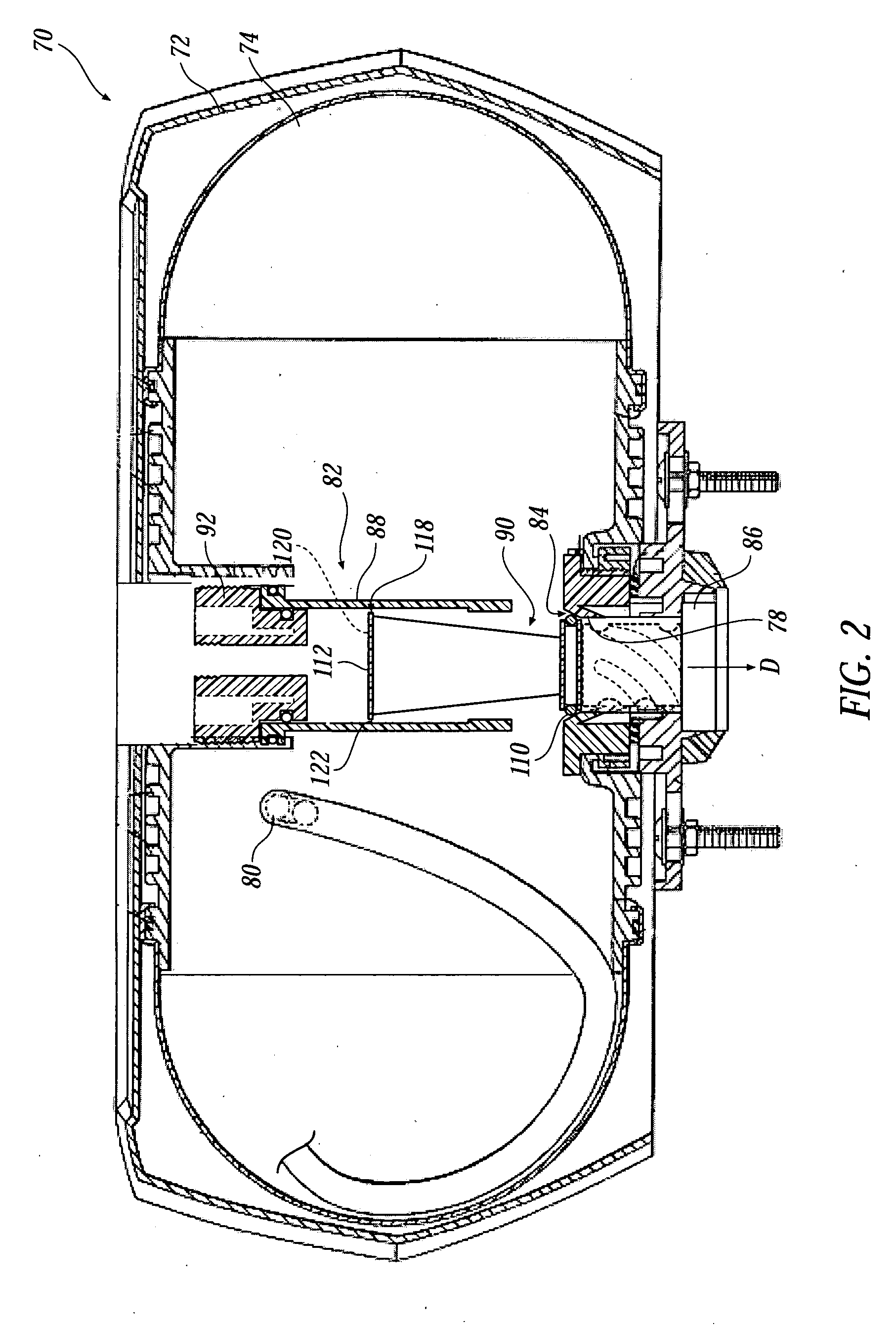
[0018]FIG. 2 illustrates a pressure assisted toilet flush system 70 in accordance with an embodiment of the present invention. The system 70 includes a vessel, or pressure tank, 74 having a discharge outlet 78 and an inlet 80, and a flush cartridge 82. Discharge outlet 78 is preferably defined in part by a frusto-conical interior surface 84 and a generally cylindrical surface 86, as discussed below.

[0019] With reference to FIGS. 2 and 3, flush cartridge 82 includes a jacket, or outer housing, 88, a flush valve 90, and a top cap 92. Outer housing 88 includes a cylindrical body (or jacket) 94 that extends from a top end 96 to a bottom end 98, and an internal surface 100. Top end 96 defines a larger inside diameter than bottom end 98, and internal surface 100 is accordingly tapered from top end 96 to bottom end 98. Internal surface 100 includes a retaining element 104 disposed thereon and extending inwardly from the internal surface 100. Preferably, retaining element 104 is three equa...


PUM


Abstract

A pressure assisted toilet flush cartridge that reduces noise output by controlling water flow. One aspect of the noise reduction is to reduce the initial discharge increase in flow rate. Another aspect is to create a vortex in discharge water to reduce cavitation and quiet the discharged water flow through the bowl.

Description

TECHNICAL FIELD [0001] The present invention relates to a pressure assisted toilets, and more specifically to a flush cartridge for a pressure assisted toilet. BACKGROUND OF THE INVENTION [0002] A pressure assisted toilet system typically includes a vessel, a supply system and a flush cartridge. The supply system typically includes a backflow prevention and a pressure regulator to ensure that the vessel is maintained below a desired pressure. Since the vessel is fully sealed, it retains the supply pressure after each flush cycle refill. This supply pressure, typically 45-55 psi, pressurizes the pressure tank to its prescribed level and provides a motive force for a subsequent flush of a toilet bowl. Prior art pressure assisted toilet systems are found in U.S. Pat. Nos. 4,223,698, 5,361,426, and RE37,921 the disclosures of which are hereby incorporated by reference in their entireties. [0003]FIG. 1 illustrates a prior art pressure assisted toilet system 20. System 20 is typically enc...

Claims


Application Information

Patent Timeline
IPC IPC(8): E03D1/00
CPCE03D3/10
Inventor MARTIN, RAYMOND BRUCE
Owner WATER CONTROL TECH CORP
Why Eureka
Try Eureka