Deaeration device and ultrasonic cleaning device using the same

a cleaning device and aeration device technology, applied in the direction of liquid degasification, cleaning process, separation process, etc., can solve the problems of reducing sound pressure and cleaning capability, energy loss, etc., and achieve the effect of reducing costs, simplifying the entire ultrasonic cleaning device, and removing easily and surely

Active Publication Date: 2006-12-21
KAIJOO KK
View PDF8 Cites 15 Cited by
  • Summary
  • Abstract
  • Description
  • Claims
  • Application Information

AI Technical Summary

Benefits of technology

[0034] According to the deaeration device in (1), since the dissolved air in the cleaning liquid is emerged as air bubbles using cavitation to be separated and ejected from the cleaning liquid, the dissolved air can be easily and surely removed from the cleaning liquid even with an extremely simple structure. Therefore, constitution of the deaeration device and hence the entire ultrasonic cleaning device can be simplified, and costs can be reduced.
[0035] According to the deaeration device in (2), since the deformable elastic tube is used and the throttle portion having an arbitrary size of inside sectional area can be formed by pressing the elastic tube with the tube-sectional-area varying mechanism, bubbling of the dissolved air in the cleaning liquid can be freely controlled. Also, if fluoro-rubber or the like is used as a material for the elastic tube, not only water-based cleaning liquid but hydrocarbon-based or solvent-type cleaning liquid can be used.
[0036] According to the deaeration device in (3), since the undeformable rigid pipe is used and the throttle portion is formed by narrowing the diameter of the rigid pipe at an appropriate position thereof, the deaeration device with high strength and excellent durability can be obtained.
[0037] According to the deaeration device in (4), sinc

Problems solved by technology

For an industrial cleaning device, it is a crucial problem how to remove completely stains or burrs adhered to parts and members for finishing.
Diss

Method used


Image

  • Deaeration device and ultrasonic cleaning device using the same
  • Deaeration device and ultrasonic cleaning device using the same
  • Deaeration device and ultrasonic cleaning device using the same

Examples


Embodiment Construction

[0064] Preferred embodiments of the present invention will be described below referring to the attached drawings.

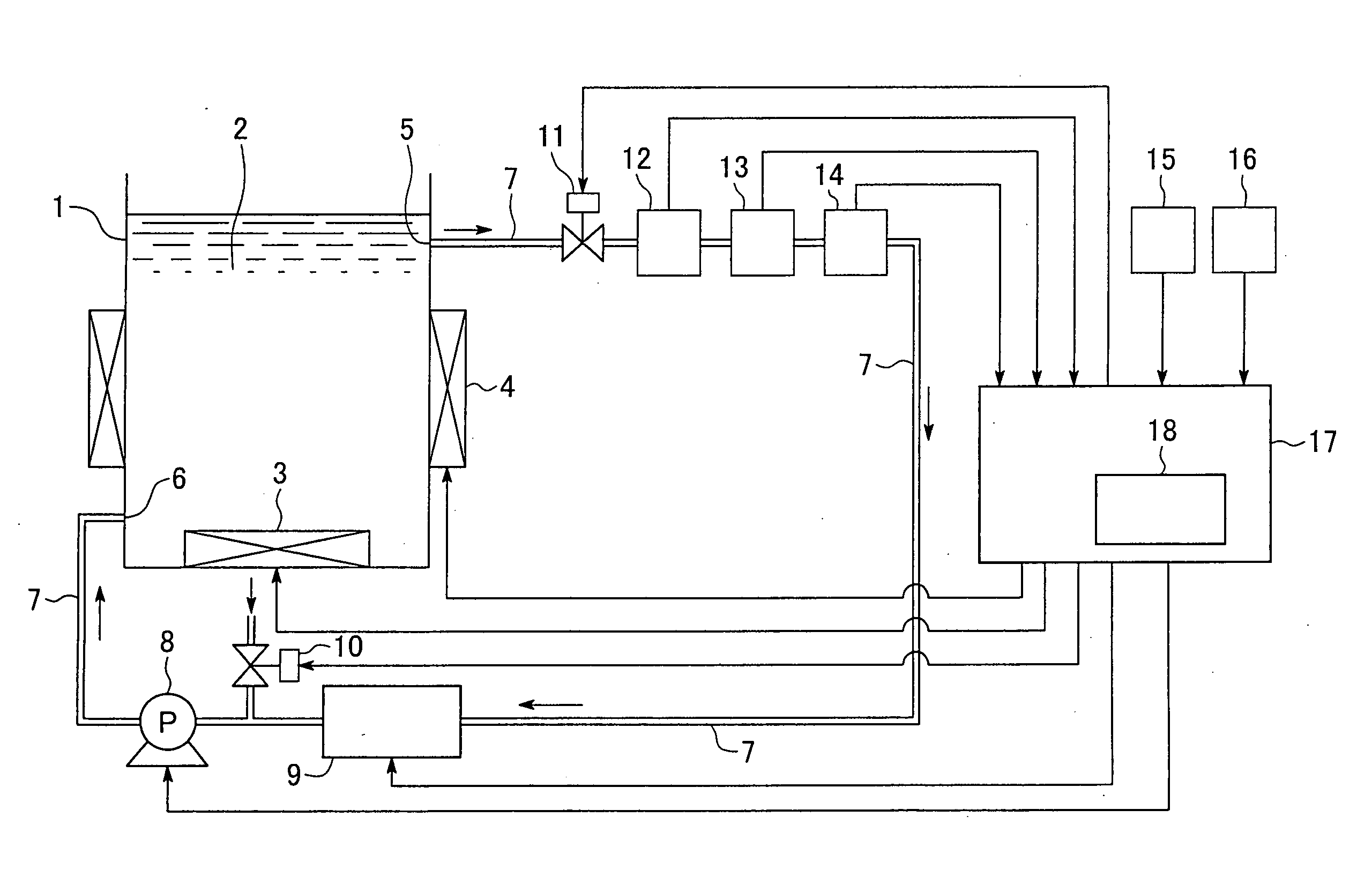
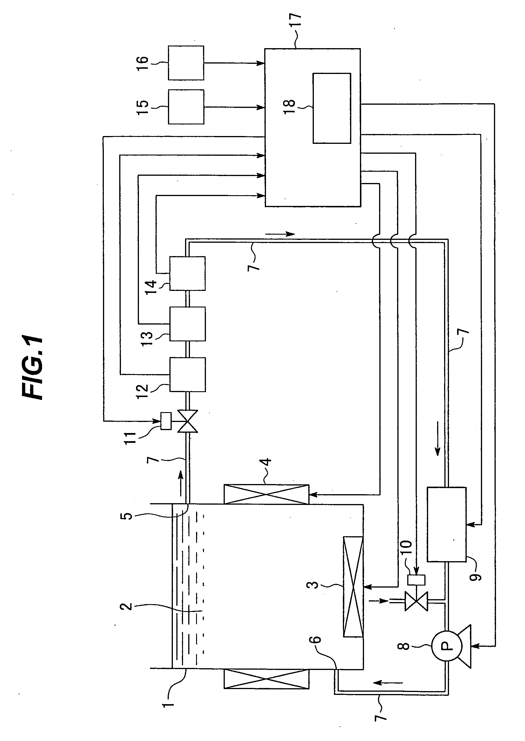
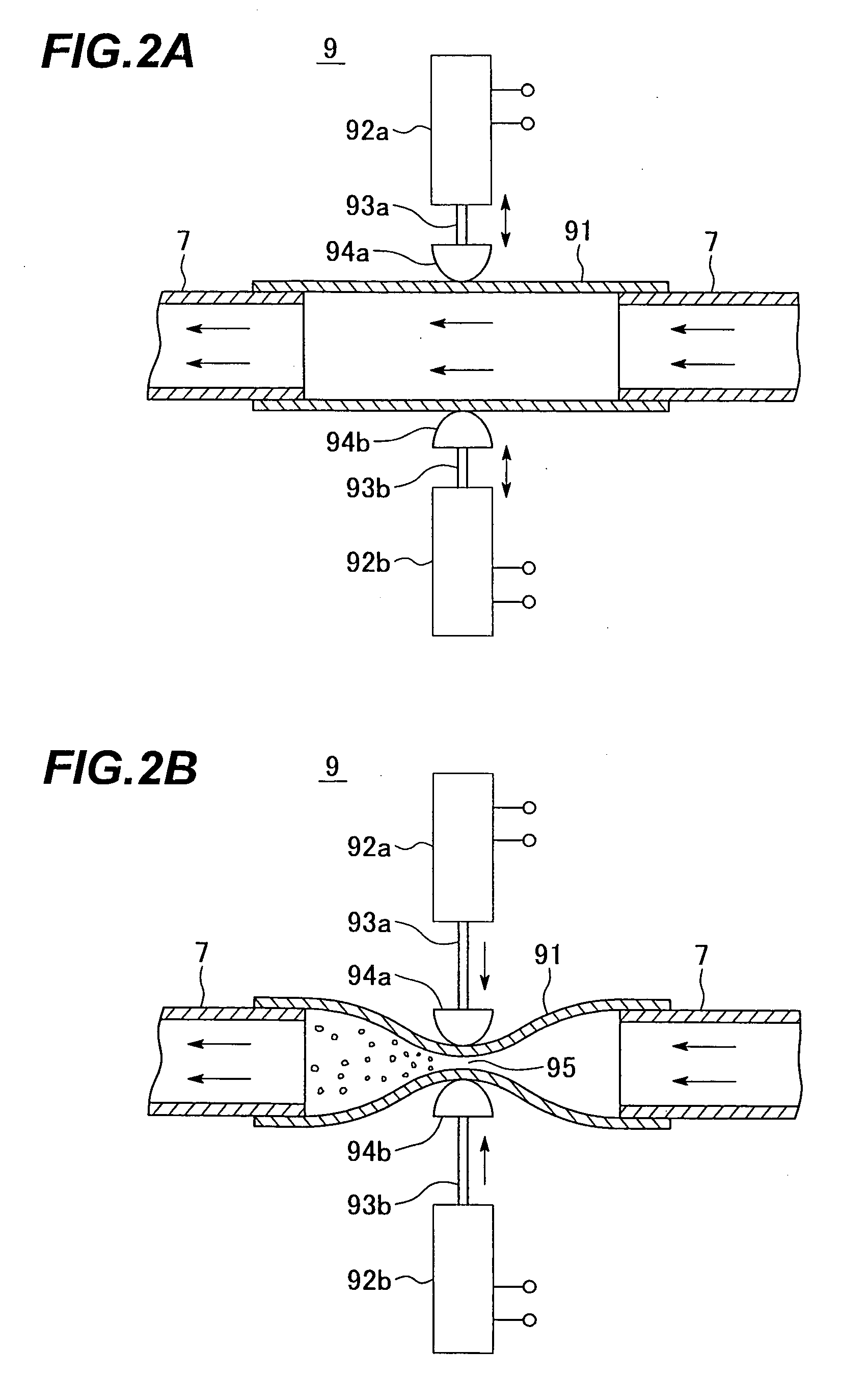
[0065]FIG. 1 is a diagram showing a preferred embodiment of the ultrasonic cleaning device according to the present invention, and FIG. 2 is a view showing constitution of a deaeration device used in this preferred embodiment.

[0066] In FIG. 1, reference numeral 1 denotes a cleaning tank filled with a cleaning liquid 2, and an ultrasonic wave generator 3 is attached to a bottom face of this cleaning tank 1. Moreover, a heater (liquid temperature control means) 4 is attached around the cleaning tank 1 so that the temperature of the cleaning liquid 2 is controllable.

[0067] A suction port 5 for the cleaning liquid is opened at an upper position of the cleaning tank 1, while a discharge port 6 is opened at a lower portion on a tank wall side opposite to the suction port 5, and a cleaning-liquid circulation path 7 is formed by connecting the suction port 5 and the discharge ...


PUM

PropertyMeasurementUnit
Concentrationaaaaaaaaaa
Flow rateaaaaaaaaaa

Abstract

A cleaning-liquid circulation path is formed so that cleaning liquid in a cleaning tank is suctioned by a circulating pump and circulated through a predetermined path and then, returned to the cleaning tank again. A deaeration device for bubbling dissolved air in the cleaning liquid by cavitation is connected on the way of the cleaning-liquid circulation path so as to bubble the dissolved air in the cleaning liquid flowing through the cleaning-liquid circulation path by the deaeration device, and the bubbled dissolved air flows back to the cleaning tank together with the cleaning liquid so that the bubbled dissolved air is ejected from the liquid surface of the cleaning tank to the outside of the tank. Moreover, a propeller-type pump is used as the circulating pump, and the dissolved air concentration of the cleaning liquid is controlled within a range of 2.5 to 3.5 mg/l.

Description

BACKGROUND OF THE INVENTION [0001] 1. Field of the Invention [0002] The present invention relates to a deaeration device for removing dissolved air in cleaning liquid and an ultrasonic cleaning device using this deaeration device. [0003] 2. Description of a Related Art [0004] For an industrial cleaning device, it is a crucial problem how to remove completely stains or burrs adhered to parts and members for finishing. An ultrasonic cleaning device has been used as one of those cleaning devices. [0005] The ultrasonic cleaning deice separates and removes stains or burrs adhered to the surface of an object to be cleaned by vibration energy of an ultrasonic wave by mounting an ultrasonic wave generator in a cleaning tank filled with cleaning liquid and by irradiating the ultrasonic wave toward the object to be cleaned which is immersed in the cleaning liquid. [0006] With this type of ultrasonic cleaning device, it is known that sound pressure of the ultrasonic wave, that is, vibration en...

Claims


Application Information

Patent Timeline
IPC IPC(8): B01D47/00
CPCB01D19/0005B01D19/0052B08B3/14B08B3/12B01D19/0094B01D19/00
Inventor SAIKI, KAZUYUKIHASE, MASARUKOYAMA, KATSUHIROSAKAZAKI, KATSUTADA
Owner KAIJOO KK
Why Eureka
Try Eureka