
Ballistics panel, structure, and associated methods

a technology of ballistic panels and components, applied in the field of ballistics, can solve the problems of difficult manufacturing, difficult to stop high-energy ballistic or armor piercing rounds, and the strength advantages of such fabric materials may not be as beneficial as desired, so as to improve the performance characteristic of destroying, reduce the energy of projectiles, and reduce weight.

Inactive Publication Date: 2006-12-21
BROWN IDEA GRP LLC THE
View PDF99 Cites 21 Cited by
  • Summary
  • Abstract
  • Description
  • Claims
  • Application Information

AI Technical Summary

Benefits of technology

The present invention provides a ballistic panel and other structures with enhanced strength and protection against high-energy projectiles. The panel includes multiple layers of woven fiber material and solid objects positioned in each layer, with spacing between them. A polymeric material is positioned in the spacing between the objects. The panel can be easily and inexpensively manufactured, lightweight, and can deflect or destroy high-energy projectiles. The invention also provides methods of forming the panel and adding hollow objects to enhance its performance. The use of woven fabric layers and polymeric resin reduces weight and cost for protective applications.

Problems solved by technology

More recently, it has been recognized that use of non-woven material in different arrangements can have some benefits such as shown in U.S. Pat. No. 5,736,474 by Thomas titled “Multi-Structured Ballistic Material.” Applicants, however, have recognized that any strength advantages of such fabric materials may not be as beneficial as desired.
For example, although such fabric materials may be breathable to certain degree, such fabric materials may have difficulty stopping high energy ballistic or armor piercing rounds and may be difficult to manufacture.
Applicants have also recognized that such armor or panels also may be difficult to manufacture and that a simpler and more effective solution for ballistic armor is still desired and needed for many applications and that the type of objects described may have geometric alignment limitations which need enhancement.

Method used


Image

  • Ballistics panel, structure, and associated methods
  • Ballistics panel, structure, and associated methods
  • Ballistics panel, structure, and associated methods

Examples


Embodiment Construction

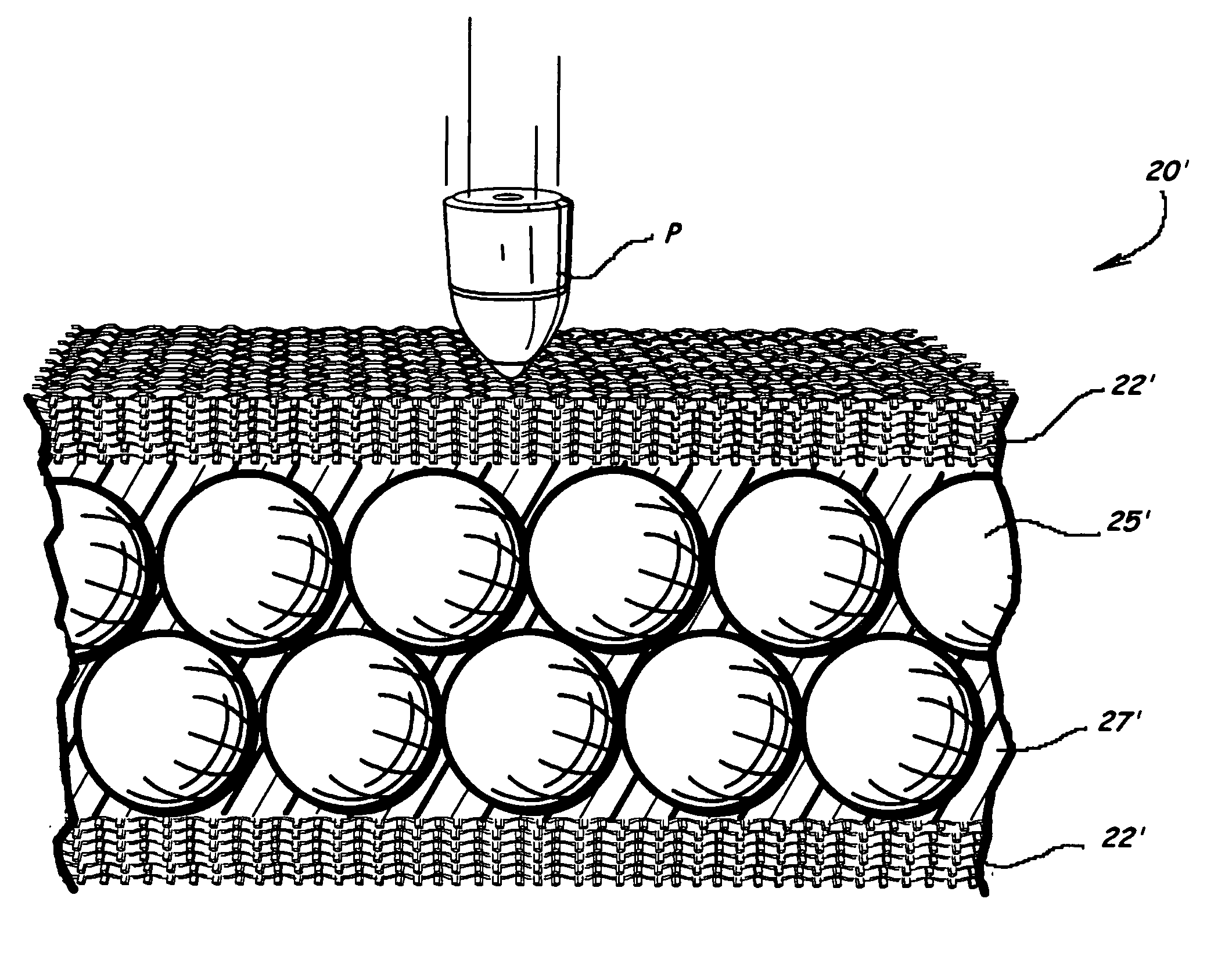
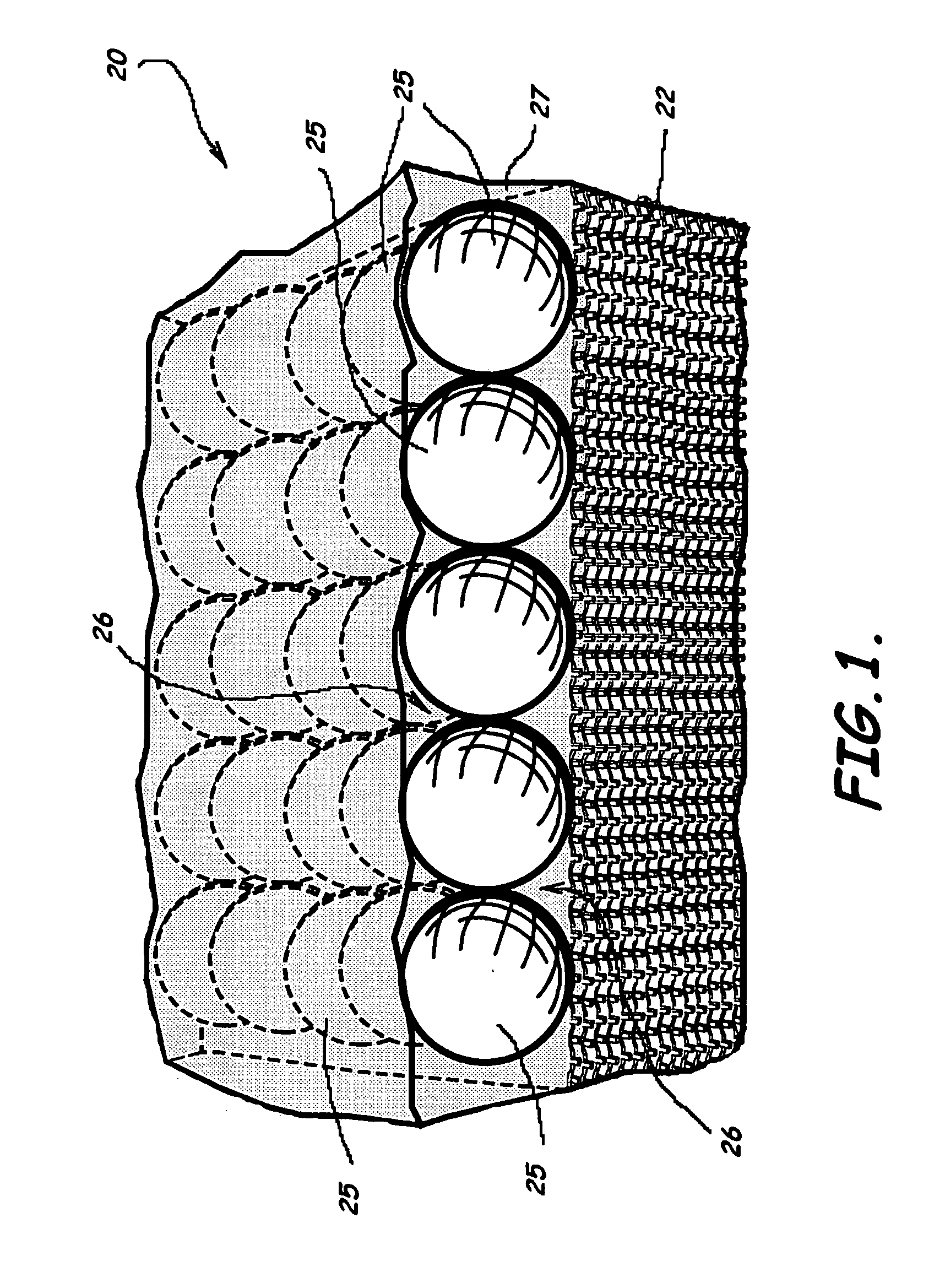
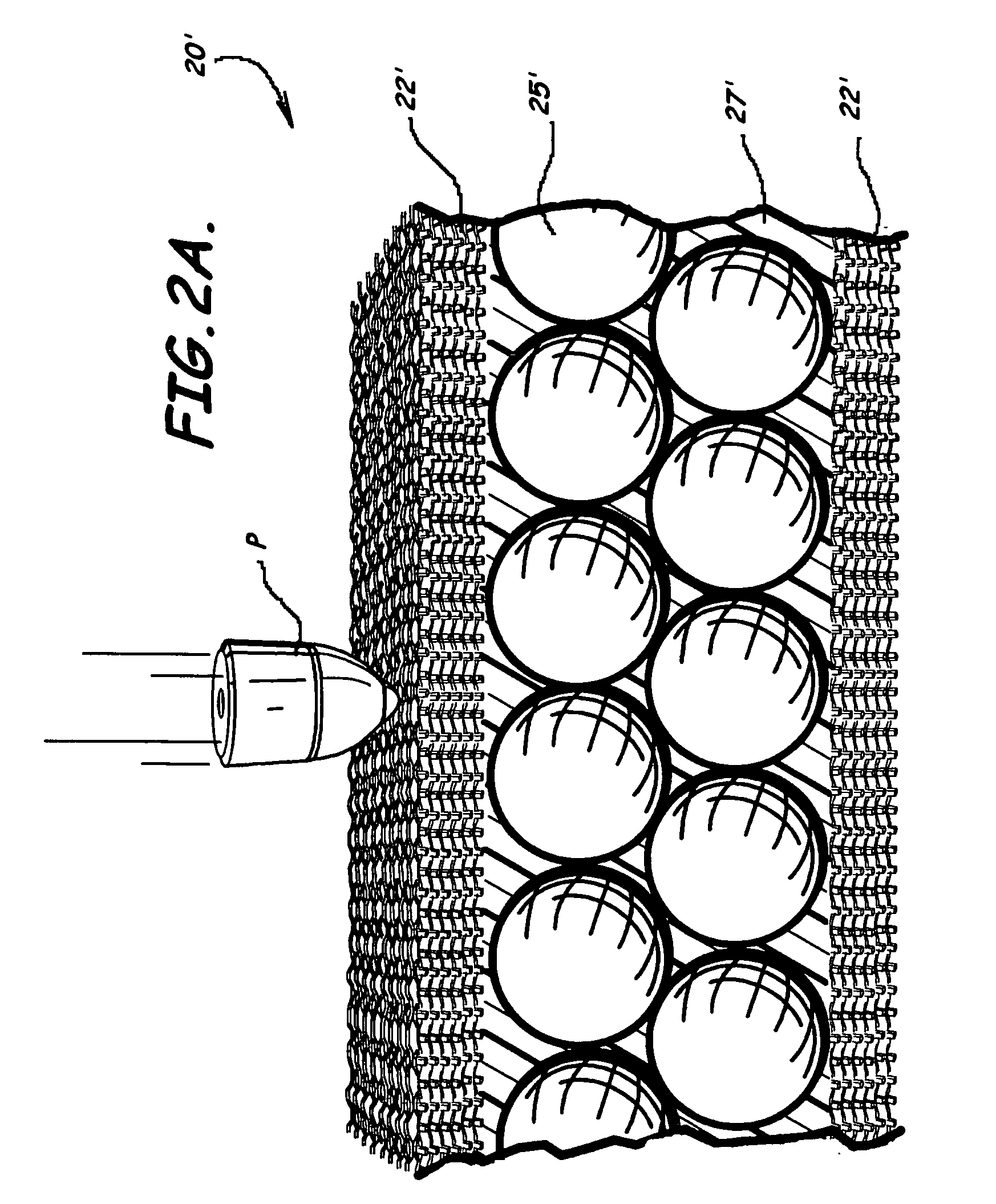
[0047] The present invention now will be described more fully hereinafter with reference to the accompanying drawings in which embodiments of the invention are shown. This invention, however, may be embodied in many different forms and should not be construed as limited to the embodiments set forth herein; rather, these embodiments are provided so that this disclosure will be thorough and complete, and will fully convey the scope of the invention to those skilled in the art. Like numbers refer to like elements throughout, and prime or double prime notation where used in association with numbers indicates like elements in alternative embodiments.

[0048]FIGS. 1-30 illustrate embodiments of a ballistic panel 20, 20′, 20″, 120, 220 or other structure, methods of forming a ballistic panel, methods of destroying a projectile P, P′ and other methods according to the present invention. These embodiments of a ballistic panel have a plurality of hard objects 25, 25′, 25″, 25a, 25b, 25c, 125, ...


PUM

PropertyMeasurementUnit
distanceaaaaaaaaaa
distanceaaaaaaaaaa
distanceaaaaaaaaaa

Abstract

A ballistic structure and associated methods of forming and using the same are provided. An embodiment of method of forming a ballistic structure includes positioning at least one layer of a plurality of substantially solid objects to overlie and contact a plurality of fabric layers. The plurality of objects is being positioned in each layer so that spacing occurs between each of the plurality of objects. The method can also include positioning a resin material in the spacing between each of the plurality of objects and to contact at least an innermost layer of the plurality of woven fabrics and heating the resin material to thereby cure the resin material.

Description

RELATED APPLICATIONS [0001] The present application claims priority to and the benefit of U.S. Provisional Patent Application Ser. No. 60 / 646,269 filed on Jan. 24, 2005 titled “Ballistics Panel, Structure, and Associated Methods” and which is incorporated herein by reference in its entirety. The present application is also related to co-pending U.S. Non-Provisional Patent Application by the same inventors titled “Ballistics Panel, Structure, and Associated Methods” filed the same day as this application, and which is also incorporated herein by reference in its entirety.BACKGROUND OF THE INVENTION [0002] 1. Field of the Invention [0003] The present invention relates to ballistics and, more particularly, to panels, clothing and other structures to reduce impact of ballistics and related methods. [0004] 2. Description of Related Art [0005] Armor and other protective materials have been used for years to protect individuals and equipment from damage by ballistics, projectiles, and othe...

Claims


Application Information

Patent Timeline
Patent Type & Authority Applications(United States)
IPC IPC(8): B29C43/02
CPCB29C70/088B29C70/22B29C70/865B29L2031/777B29K2277/10B29K2709/02B29K2995/0089B29K2075/00
Inventor BROWN, DAVID WALTERGHETTI, WILLIAM MARCUS
Owner BROWN IDEA GRP LLC THE
Learn More