
Hoist ring

Inactive Publication Date: 2006-12-21
MA SHU LAN
View PDF12 Cites 1 Cited by
  • Summary
  • Abstract
  • Description
  • Claims
  • Application Information

AI Technical Summary

Benefits of technology

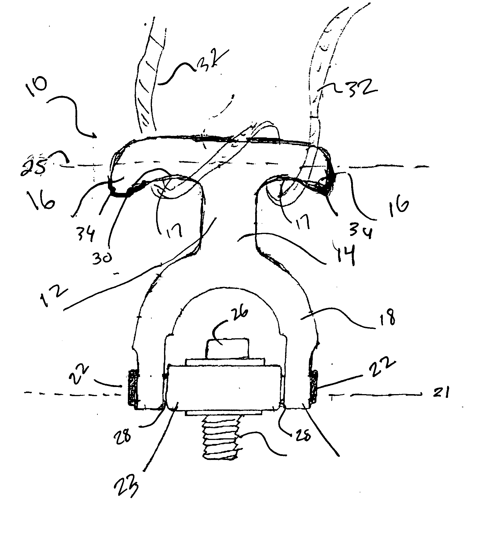
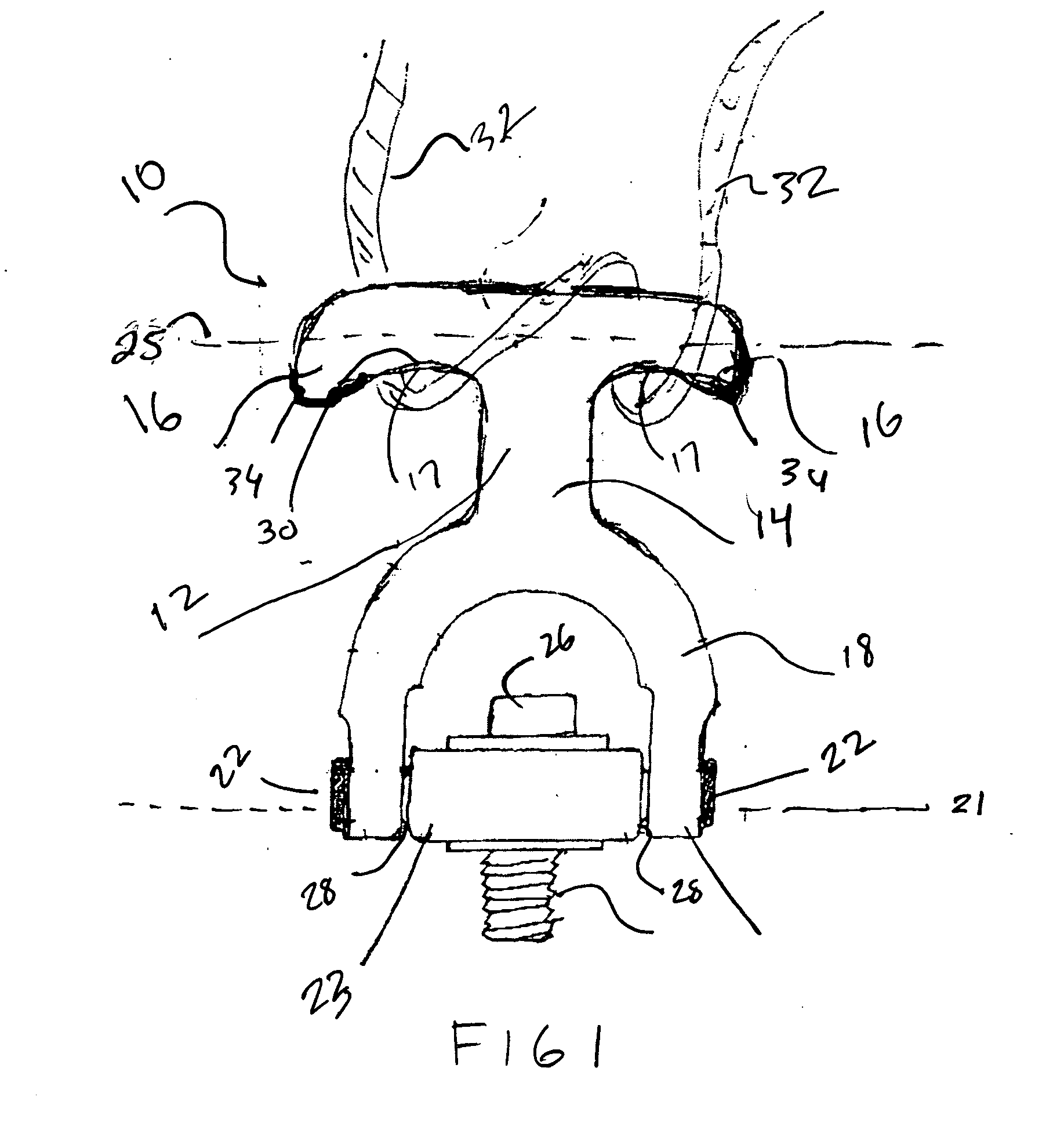
[0015] It is another object of this invention to provide a hoist ring that provides for frictional engagement of the lifting cable or rope at two underside points and one top point of contact to maximize stability and engagement of the hoist ring to the lifting cable or rope.
[0016] It is still another object of this invention to provide such a hoist ring that allows easy access to the bolt or other means of cooperative engagement to the machine, without disassembling the hoist ring.
[0017] It is an additional object of this invention to provide a hoist ring that allows for a swivelled engagement of the body portion to the cable engaging portion in a fashion that maximizes load lifting capability.
[0018] It is yet another object of this invention to provide such a hoist ring which additionally has a shape that prevents the frictionally engaged rope or lifting cable from sliding off.

Problems solved by technology

While such equipment while being large and heavy, most such equipment performs complex physical tasks that require complex and highly accurate movement by the equipment.
Consequently, the act of moving such machinery is frequently a delicate maneuver due to the need to protect the equipment from jarring, dropping, and other pitfalls that could ruin its ability to function.
However, the weight and bulk of this type of heavy equipment naturally make it hard to handle.
A problem with this conventional arrangement occurs from the constant need to run the cable or rope used to lift the hoist ring and engaged machine, through the closed eye formed by the “U” shaped ring engaged to the hoist ring body.
The constant need to thread the cable or rope through the eye for engagement, and back out of the eye for disengagement, can be tedious and time consuming thereby complicating the delicate and dangerous job of hoisting and moving extremely heavy equipment.
In one embodiment a hook replaces the eye, however the hook offers only one contact point for the cable rendering it less stable.
However, Teutsch places the hook such that it must be removed to engage the hoist to the machine to be lifted, and the hook only offers one point of contact to a cable or rope lessening stability.
However Ratcliff severely limits the lifting capacity of the hoist ring with this engagement and offers only one frictional engagement for the cable.

Method used


Image

  • Hoist ring
  • Hoist ring
  • Hoist ring

Examples


Embodiment Construction

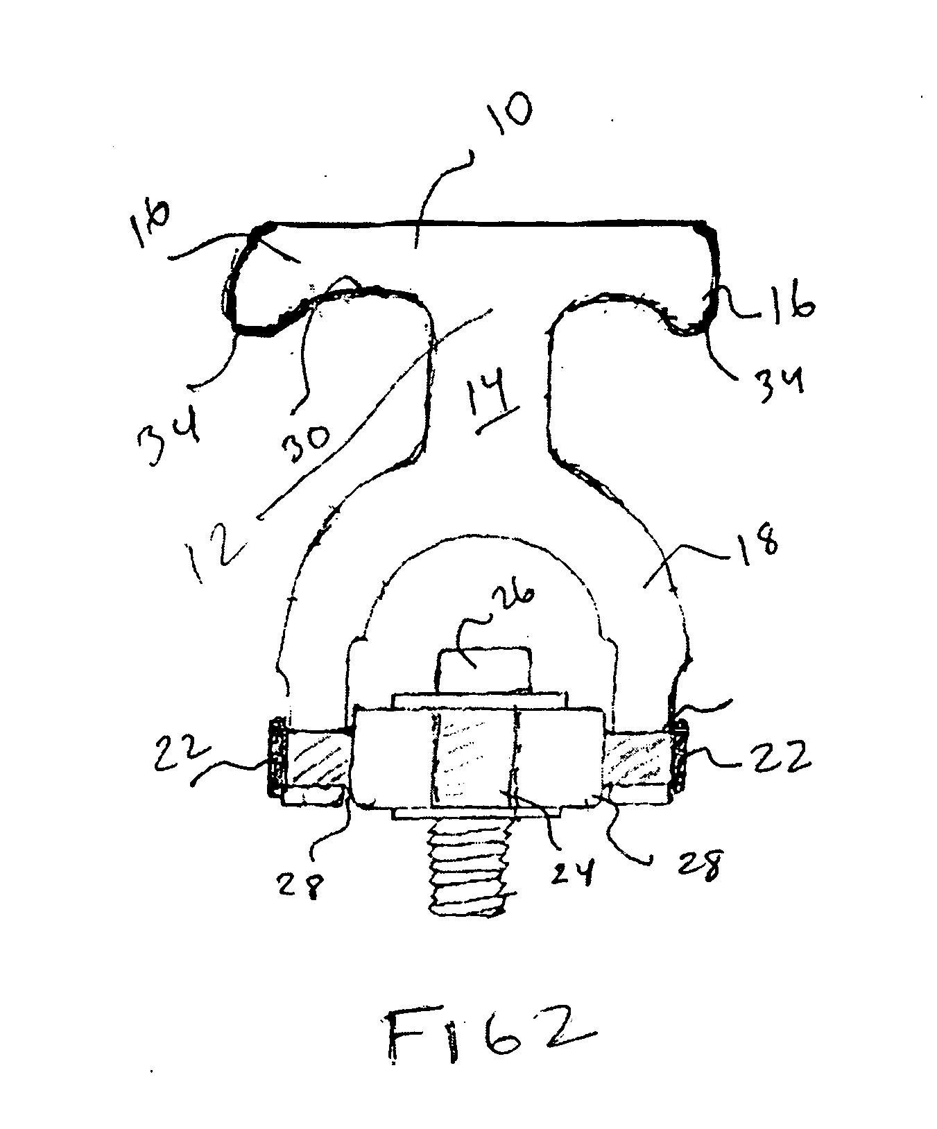
[0024]FIG. 1 depicts the disclosed device 10 assembled and ready for engagement to machinery or another load to be lifted. The device 10 features two main components. An engagement member 12 preferably of unitary construction by forging or stamping, has a generally “T” shaped distal or first end and a generally “U” shaped attachment end. The engagement member 12 is formed of a central member 14 which is attached to a pair of support members 16 which extend from the upper or distal end of the end of the central member 12 opposite an engagement end with the central member 12. The engagement end of the central member 14 is engaged at a central point of a substantially “U” shaped ring member 18.

[0025] The ring member 18 has two ends each having an aperture 20 communicating therethrough. The apertures 20 are sized for rotational engagement with the exterior of bolts 22 therethrough. The bolts are adapted for cooperative engagement into the sides of a body 23 which is thereby rotationall...


PUM


Abstract

An improved hoist ring for lifting of equipment or heavy loads adapted for engagement thereto. The device features an attachment end which allows for serpentine three point engagement of the hoist ring to a tether such as a looped lift cable or rope. The engagement eliminates the need to thread the tether through an eye or disconnect the two downward leads of the tether from each other or the lift. Shoulders formed from the lower surface of a “T” shaped engagement member also prevent the lifting cable from sliding off the ends.

Description

FIELD OF THE INVENTION [0001] The disclosed device relates hoist rings. More particularly it relates to a hoist ring that is typically used to lift very heavy equipment by cooperative engagement of the hoist ring to the equipment being lifted. In conventional use, such devices have a body portion that is threaded or otherwise co-operatively engaged with the equipment being lifted using a bolt through a center aperture in the body portion. The body portion is cooperatively with a closed ring member which engages protruding flanges which are threaded into the sides of the body portion. [0002] Engagement of the ring member to a lifting device such as a hoist or crane is usually accomplished by securing a cable or rope through the eye of the ring member which can be very time consuming especially when multiple pieces of equipment or freight are being lifted and must be engaged and then disengaged from the lift cable. The device herein replaces the conventional closed eye ring member wit...

Claims


Application Information

Patent Timeline
IPC IPC(8): B66C1/66
CPCB66C1/66
Inventor MA, SHU LAN
Owner MA SHU LAN
Learn More