Coupled FBAR filter

a filter and fbar technology, applied in piezoelectric/electrostrictive device manufacture/assembly, electrical apparatus, electric/electrostrictive device manufacturing/assembly, etc., can solve the problems of increasing loss, increasing loss, narrowing of resonant frequency band, etc., and achieves the effect of controlling impedance and superb characteristics

Inactive Publication Date: 2006-12-21
PANASONIC CORP
View PDF2 Cites 32 Cited by
  • Summary
  • Abstract
  • Description
  • Claims
  • Application Information

AI Technical Summary

Benefits of technology

[0021] Therefore, an object of the present invention is to provide a balanced/unbalanced type coupled FBAR filter efficie...

Problems solved by technology

For this reason, the charge generated in the first vibration section cannot be efficiently used in the second vibration section, which increases the loss and narrows the resonant frequency band.
The balanced/unbalanced type coupled FBAR filter 900 can significantly convert the impedance, but has a problem that the loss is increased and the resonant frequency band is narrowed.
Therefore, the charge generated...

Method used


Image

  • Coupled FBAR filter
  • Coupled FBAR filter
  • Coupled FBAR filter

Examples


first embodiment

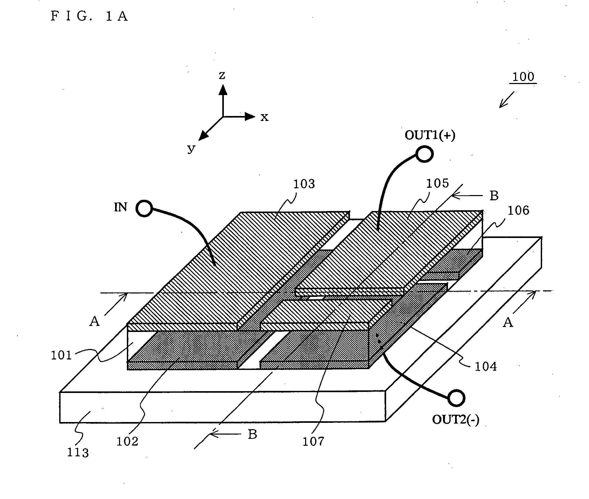
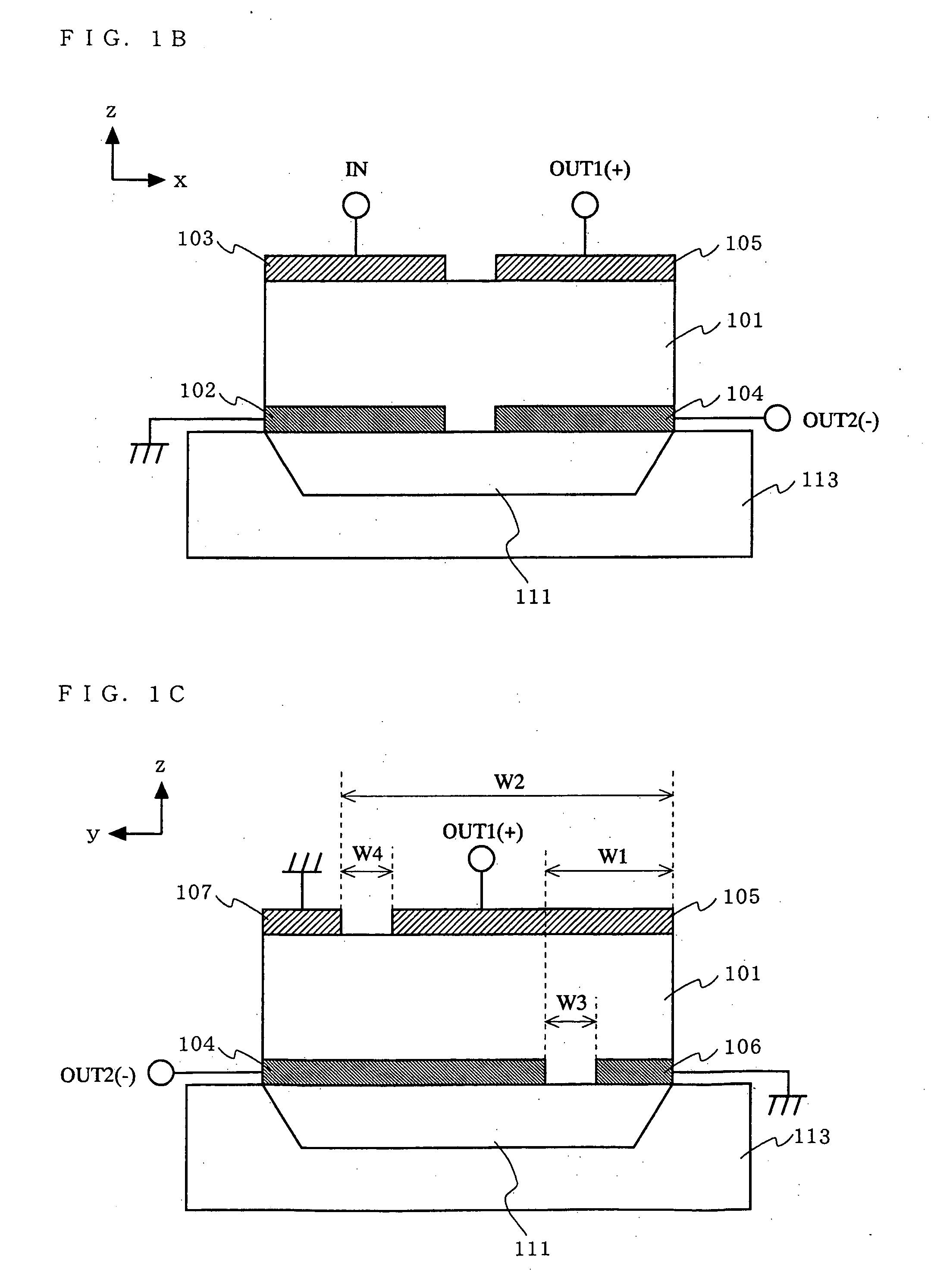
[0057]FIG. 1A is an isometric view showing a structure of a balanced / unbalanced type coupled FBAR filter 100 according to a first embodiment of the present invention. FIG. 1B is a cross-sectional view of the balanced / unbalanced type coupled FBAR filter 100 shown in FIG. 1A taken along line A-A. FIG. 1C is a cross-sectional view of the balanced / unbalanced type coupled FBAR filter 100 shown in FIG. 1A taken along line B-B. As shown in FIG. 1A through FIG. 1C, the balanced / unbalanced type coupled FBAR filter 100 includes a substrate 110, a cavity 111, a piezoelectric thin film 101, a first lower electrode 102, a second lower electrode 104, a third lower electrode 106, a first upper electrode 103, a second upper electrode 105, and a third upper electrode 107. The directions represented by x, y and z axes in FIG. 1A through FIG. 1C correspond to the directions specified below. In FIG. 1A, the piezoelectric thin film 101 is shown as being transparent for easier understanding of the struct...

second embodiment

[0083]FIG. 7A is a cross-sectional view showing a structure of a balanced / unbalanced type coupled FBAR filter 200 according to a second embodiment of the present invention. The cross-sectional view shown in FIG. 7A corresponds to the cross-sectional view shown in FIG. 1 taken along line A-A.

[0084] The balanced / unbalanced type coupled FBAR filter 200 has the following features in addition to those of the balanced / unbalanced type coupled FBAR filter 100 according to the first embodiment. [0085] 1. The first vibration section and the second vibration section are located adjacently in contact with each other with no gap therebetween. [0086] 2. The first lower electrode 102 is electrically insulated from the second and third lower electrodes 104 and 106. [0087] 3. The first upper electrode 103 is electrically insulated from the second and third upper electrodes 105 and 107. [0088] 4. The resonant frequency of the first vibration section in the thickness direction (z direction) is genera...

third embodiment

[0092] In a third embodiment, exemplary applications of a coupled FBAR filter according to the present invention will be described. FIG. 8A shows a circuit formation of a balanced / unbalanced type coupled FBAR filter according to the present invention. FIG. 8B shows a circuit formation of a balanced / balanced type coupled FBAR filter according to the present invention. Hereinafter, a coupled FBAR filter according to the present invention will be represented with the circuit formation shown in FIG. 8A or FIG. 8B.

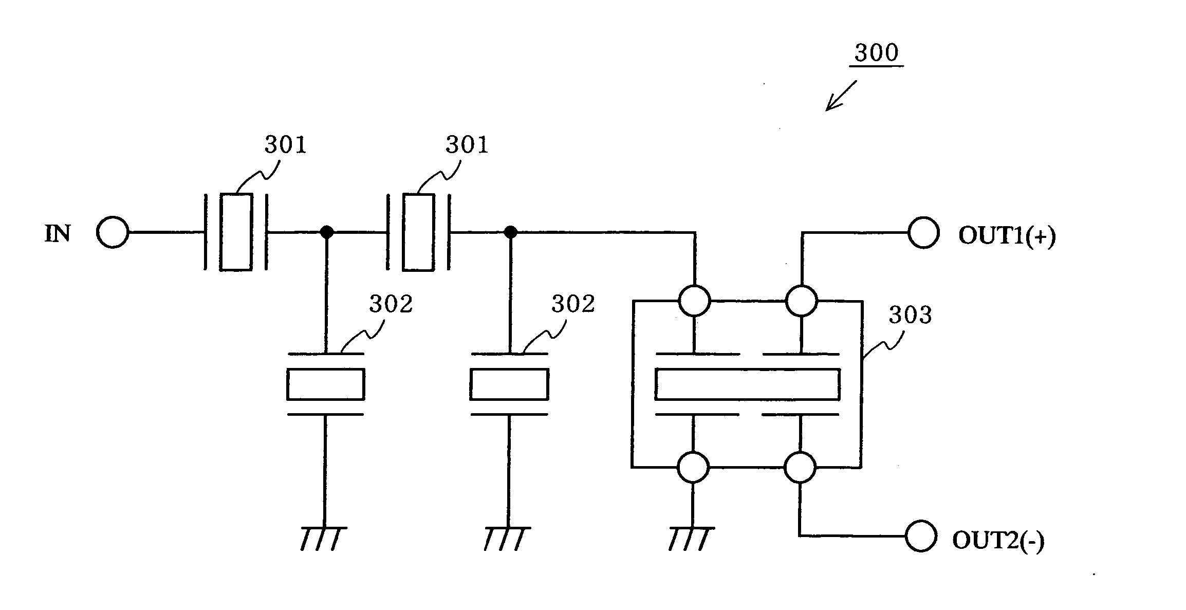
[0093]FIG. 9A is a circuit diagram of a ladder-type filter 300 including a balanced / unbalanced type coupled FBAR filter according to the present invention. As shown in FIG. 9A, the ladder-type filter 300 includes a plurality of FBAR filters 301 connected in series, a plurality of FBAR filters 302 connected in parallel to the plurality of FBAR filters 301, and a balanced / unbalanced type coupled FBAR filter 303 according to the present invention connected to an output. The FBAR ...


PUM


Abstract

In a balanced/unbalanced type coupled FBAR filter 100, an area size of a first lower electrode 102 is generally equal to a total area size of second and third lower electrodes 104 and 106 and an area for isolating the second and third lower electrodes 104 and 106. An area size of a first upper electrode 103 is generally equal to a total area size of second and third upper electrodes 105 and 107 and an area for isolating the second and third upper electrodes 105 and 107. The third lower electrode 106 and the second upper electrode 105 are located to face each other, and the third upper electrode 107 and the second lower electrode 104 are located to face each other. Apart of the second lower electrode 104 and a part of the second upper electrode 105 are located to face each other.

Description

BACKGROUND OF THE INVENTION [0001] 1. Field of the Invention [0002] The present invention relates to a coupled FBAR filter usable for balancing; and a ladder-type filter, a duplexer and a communication device including such a coupled FBAR filter. [0003] 2. Description of the Background Art [0004] Conventionally, filters mounted on wireless communication devices such as cellular phones include dielectric filters, laminated filters and acoustic filters. Known acoustic filters include a monolithic crystal filter (MCF) using a plurality of modes of a bulk wave and a surface acoustic wave filter (SAW filter). Recently, filters are required to have a smaller size, to provide a higher performance and to be usable at a higher frequency. As a device for fulfilling these requirements, a film bulk acoustic resonator filter (FBAR filter) using a bulk wave of a piezoelectric thin film has been developed. As an FBAR filter, a coupled FBAR filter realized by multiplexing a plurality of modes is pr...

Claims


Application Information

Patent Timeline
IPC IPC(8): H03H9/70H03H9/58H01L41/22H01L41/29
CPCH03H9/0004H03H9/0095H03H9/564H03H9/02157H03H9/0207
Inventor IWASAKI, TOMOHIRONAKATSUKA, HIROSHIONISHI, KEIJINAKAMURA, HIROYUKI
Owner PANASONIC CORP
Why Eureka
Try Eureka