Scanning display

a scanning display and display screen technology, applied in the field of scanning displays, can solve the problems of reducing the moving speed of the beam spot on the retina, affecting the accuracy of scanning devices, so as to reduce the noise of scanning devices

Inactive Publication Date: 2006-12-21
CANON KK
View PDF12 Cites 13 Cited by
  • Summary
  • Abstract
  • Description
  • Claims
  • Application Information

AI Technical Summary

Benefits of technology

[0008] It is an illustrative object of the present invention to reduce a noise of a scanning device in a scanning display that scans two or more scanning areas by using plural light sources and enables one image to be recognized.

Problems solved by technology

A higher scanning frequency of the scanning device makes its manufacture difficult.
However, the scanning frequency of the scanning device lowered by segmenting one screen into plural areas would retard the beam scanning speed, and lower the moving speed of the beam spot on the retina.

Method used


Image

  • Scanning display
  • Scanning display
  • Scanning display

Examples


first embodiment

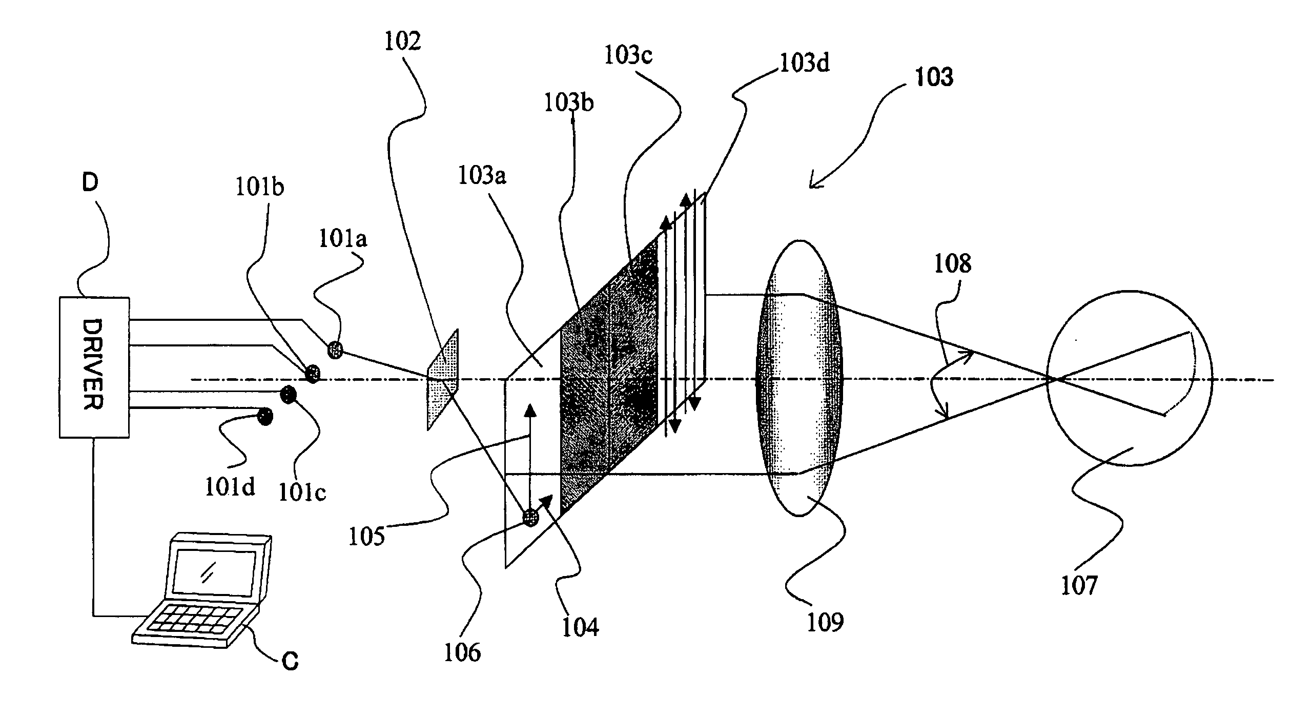
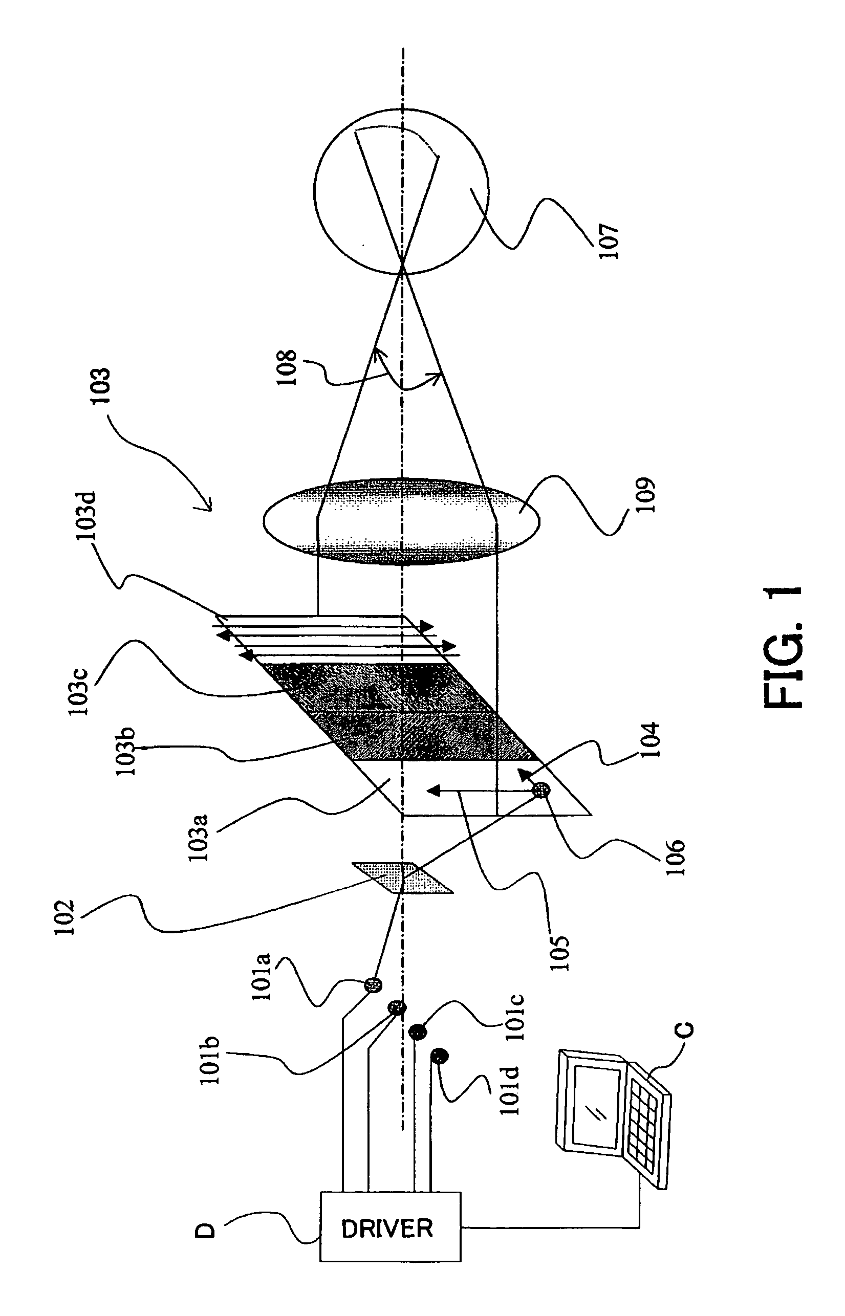
[0027]FIG. 1 shows a schematic structure of a scanning display according to a first embodiment of the present invention. The scanning display is used for a head mount display that is attached to a viewer's head and enables him to view motion and still images. Alternatively, the scanning display may be mounted as electronic viewfinder in a video camcorder and a digital camera.

[0028] In FIG. 1, 101a to 101d denote light sources, such as an LED, a laser diode, and a lamp. 102 denotes a scanning device (or a scanner) that scans the lights from the light sources 101a to 101d in two-dimensional directions. The scanning device of this embodiment includes a rotatable plane mirror. 109 denotes an ocular optical system (eyepiece) that magnifies a beam to be scanned by the scanning device 102, and introduces the beam to a viewer's eye or retina 107.

[0029] For simplified description, FIG. 1 omits an optical system that converts a divergent light from the light source into an approximately col...

second embodiment

[0055] In the second embodiment of the present invention, similar to the first embodiment, the horizontal view angle Fov (or the entire angular field of view in the low-speed scanning direction) is 24°, the horizontal resolution Res is 800 pixels, and twelve scanning areas are arranged in the horizontal direction. The scanning display is configured similar to that of the first embodiment (FIG. 1), and common elements are designated by the same reference numerals as those in the first embodiment.

[0056] In the low-speed scanning direction, the scanning device 102 is driven in a sine waveform shown in FIG. 7. The constant a is 2.5 (time use efficiency k=0.8). In that case, the equation (2) meets FR≧(600×12) / (2 / 0.8×24)=120 (Hz). Therefore, no image drops occur when the scanning frequency in the low-speed scanning frequency is 120 Hz or greater.

[0057] A scanning frequency in a perpendicular direction as a high-speed scanning direction in which scanning is faster than that in the horizo...

third embodiment

[0068] The third embodiment of the present invention discusses a scanning display that sets, similar to the first embodiment, a low-speed scanning direction to the horizontal direction, and the number of pixels in the low-speed scanning direction to 2,160 pixels. Since the minimum resolution of the human eye is about 1 minute, the minimum resolution of the human eye accords with a size of one pixel when the horizontal view angle is 36°. Accordingly, this embodiment sets the horizontal view angle to 36°. The scanning display is configured similar to that of the first embodiment (FIG. 1), and common elements are designated by the same reference numerals as those in the first embodiment.

[0069] Assume that plural scanning areas are arranged in the low-speed scanning direction, and the scanning device 102 is driven in a saw tooth waveform in the low-speed scanning direction. Also assume that the frequency FR is 60 Hz, and the constant α is 1.25 (=1 / k: time use efficiency k=0.8). From th...


PUM


Abstract

A scanning display includes plural light sources, and a scanner for two-dimensionally scanning a scanning area in a scanning surface from lights from the plural light sources, wherein the scanner scans plural partial scanning areas that are arranged in a first direction within a range corresponding to the scanning area, by using mutually different lights from the plural light sources, the scanner scanning each partial scanning area at a first speed in the first direction and at a second speed higher than the first speed in a second direction different from the first direction, and wherein FR≧(ω×Z)/(ω×Fov) is met, where FR is a scanning frequency (Hz) of the light in the first direction of the partial scanning area, ω is an oculomotor angular speed (°/sec) in a saccade, Z is the number of partial scanning areas arranged in the first direction in the scanning area, α is a constant relating to an effective scanning period in one scanning period in the first direction, and Fov is an entire view angle (°) in the first direction

Description

BACKGROUND OF THE INVENTION [0001] The present invention relates to a scanning display that scans a light in two-dimensional directions and enables a viewer to recognize an image. [0002] Many retinal scanning displays have conventionally been proposed which scan a light beam from a light source in a viewer's retina at a high speed, and enables him to recognize an image by utilizing an afterimage effect. One retinal scanning display synthesizes plural lights from one or more light sources into one beam, and scans the beam, as disclosed in Japanese Patent Application (“JPA”) Publication No. 2004-138822. Another type scans plural areas with plural beams, and enables the viewer to recognize one image by connecting partial images of these areas, as disclosed in JPA Domestic Publication No. 2004-527793. [0003] A scanning device that operates at several kHz to several tens kHz is required in order to obtain a high-resolution image by scanning a light beam at a high speed, and such this typ...

Claims


Application Information

Patent Timeline
Patent Type & Authority Applications(United States)
IPC IPC(8): G09G3/36
CPCG02B26/0833G02B2027/0178G02B27/0172G02B26/101
Inventor YAMAMOTO, AKIRAKOBAYASHI, SHUICHI
Owner CANON KK
Why Eureka
Try Eureka