Image capture device, image capture system, and synchronizing method

Inactive Publication Date: 2006-12-21
EASTMAN KODAK CO
View PDF18 Cites 30 Cited by
  • Summary
  • Abstract
  • Description
  • Claims
  • Application Information

AI Technical Summary

Benefits of technology

[0009] According to the present invention, the detection circuit can detect the luminance change of the object in accordance with the luminance of the object to be detected

Problems solved by technology

In the case of an image capture system using image capture devices, when a special effect image such as stereoscopic or

Method used


Image

  • Image capture device, image capture system, and synchronizing method
  • Image capture device, image capture system, and synchronizing method
  • Image capture device, image capture system, and synchronizing method

Examples


Embodiment Construction

[0025] A preferred embodiment of the present invention is described below while referring to the accompanying drawings.

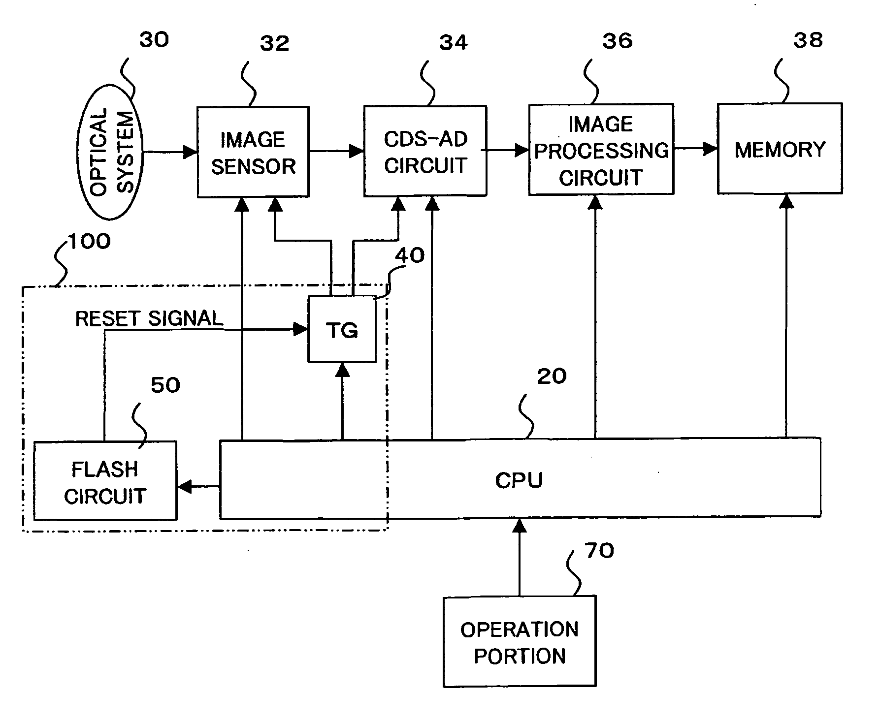
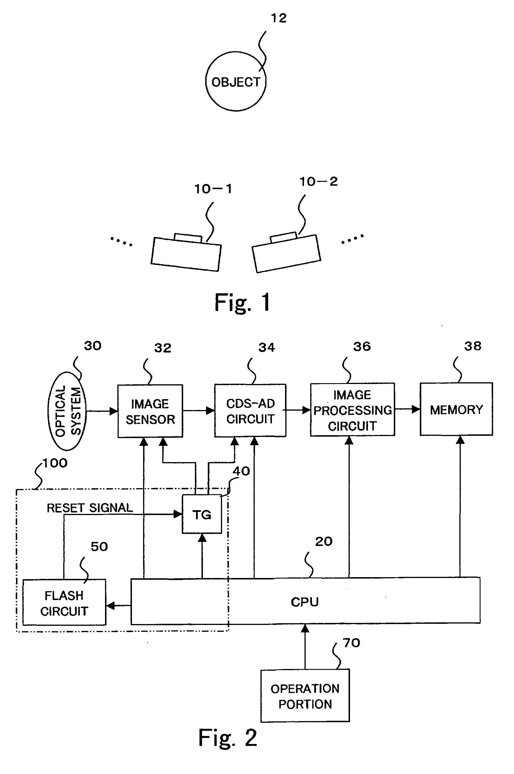
[0026]FIG. 1 is an illustration showing a schematic configuration of the image capture system of the present embodiment. As shown in FIG. 1, this image capture system comprises a plurality of image capture devices 10-1, 10-2, (hereafter generally referred to as “image capture device 10” when differentiation is unnecessary. This system is similarly applied to a circuit constituting the image capture device 10). Each image capture device 10 is synchronized to perform simultaneous or continuous photography for capturing an image of an object 12.

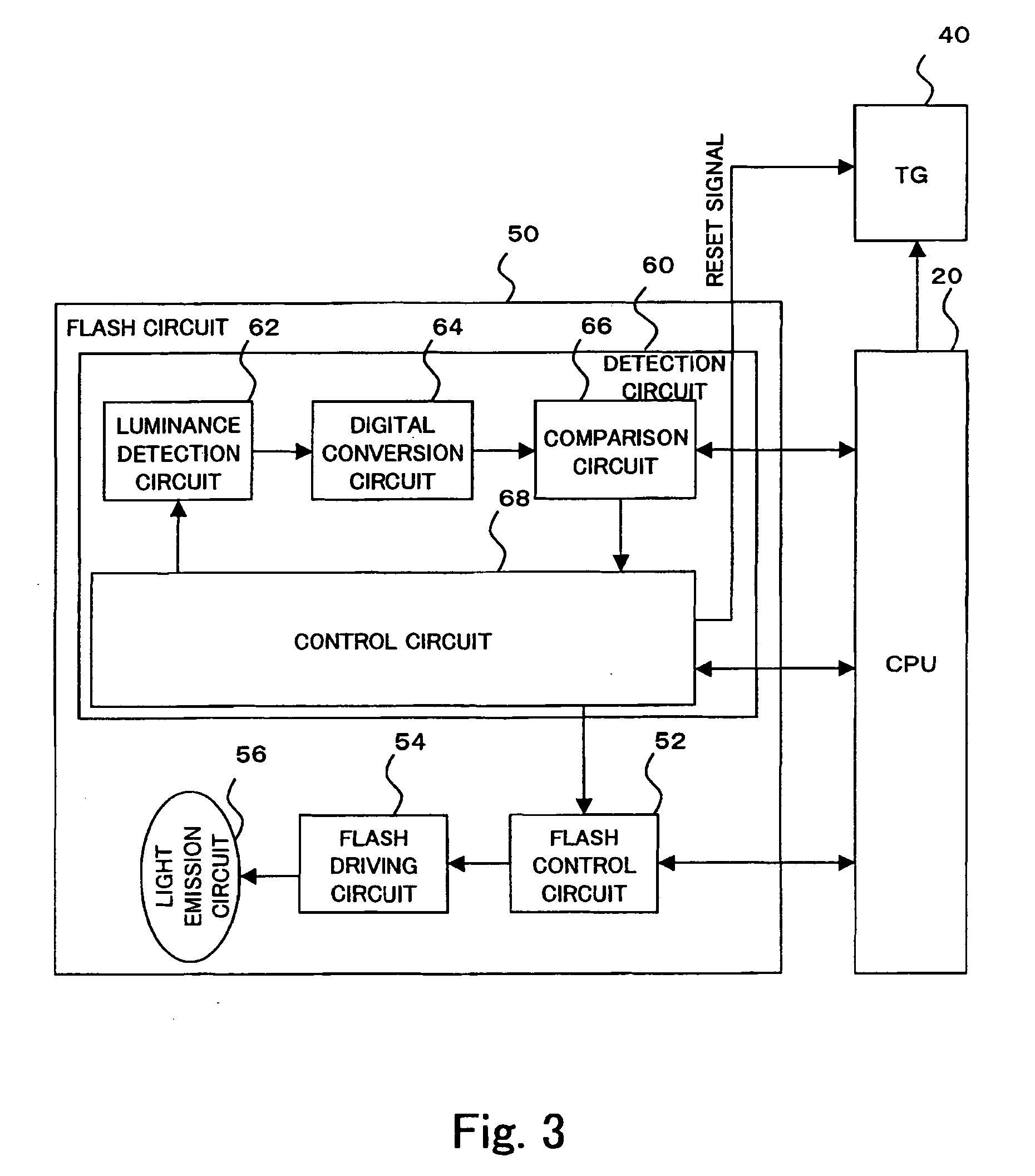
[0027] In the example of this embodiment, each image capture device 10 can operate in either of two modes, such as a main device mode and an auxiliary device mode. The image capture device 10 set to the main device mode performs pre-light emission and the image capture device 10 set to the auxiliary device mode detects the pre...


PUM


Abstract

Image capture devices are synchronized without using a communication unit for an image capture device to perform communication with other image capture device. When an image capture device 10 is set to the main device mode, it outputs a reset signal to a timing generator 40 simultaneously with the time when a flash circuit 50 performs pre-light emission and, when the image capture device 10 is set to the auxiliary device mode, the flash circuit 50 detects pre-light emission performed by other image capture device and outputs a reset signal to the timing generator 40 in accordance with the detection of the pre-light emission.

Description

FIELD OF THE INVENTION The present invention relates to the synchronization of image capture devices in an image capture system using image capture devices. BACKGROUND OF THE INVENTION [0001] Image capture systems using image capture devices are disclosed in Japanese Patent Laid-Open Publication No. 2004-048648, which discloses a system that generates special effect images, such as a stereoscopic or panoramic image, using image capture devices; and Japanese Patent Laid-Open Publication No. 2004-235786, which discloses a system set so as to light-emit only a stroboscope in accordance with a brightness illuminated to an object at the time of collaboration photographing connecting digital cameras and using a stroboscope or set so as to emit light by decreasing the stroboscope light emission quantity of each camera. It is a system in which one camera performs image capturing while the other camera emits a strobe flash, or one of a plurality of cameras performs image capturing with each ...

Claims


Application Information

Patent Timeline
IPC IPC(8): H04N5/335G03B7/16G03B7/28G03B15/05H04N5/232
CPCH04N5/232H04N5/2354H04N5/23245H04N5/23241H04N23/665H04N23/651H04N23/667H04N23/74
Inventor KANAI, KUNIHIKOASAMI, SHUJIKOBAYASHI, MASAO
Owner EASTMAN KODAK CO
Why Eureka
Try Eureka