Optical unit and image forming apparatus

Inactive Publication Date: 2006-12-21
CANON KK
View PDF4 Cites 16 Cited by
  • Summary
  • Abstract
  • Description
  • Claims
  • Application Information

AI Technical Summary

Benefits of technology

[0049] The present invention is directed to an optical unit which has high rigidity while, when a cover i

Problems solved by technology

This gives rise to the problem that the spot size on the photoconductive member of the rotating drum D is changed, or that the scanning line is deviated.
In addition to the deformation of the optical box caused by the difference in linear expansion coefficient between the components and the deformation of the optical box caused by the warp of the cover, however, there are other factors causing the deviation of the scanning line on the photoconductive member.
The other factors causing the deviation of the scanning line include a deformation of the optical box generated when the optical box is mounted to the image forming apparatus, and vibration generated by the image forming apparatus

Method used


Image

  • Optical unit and image forming apparatus
  • Optical unit and image forming apparatus
  • Optical unit and image forming apparatus

Examples


first exemplary embodiment

(Scanning Optical Unit)

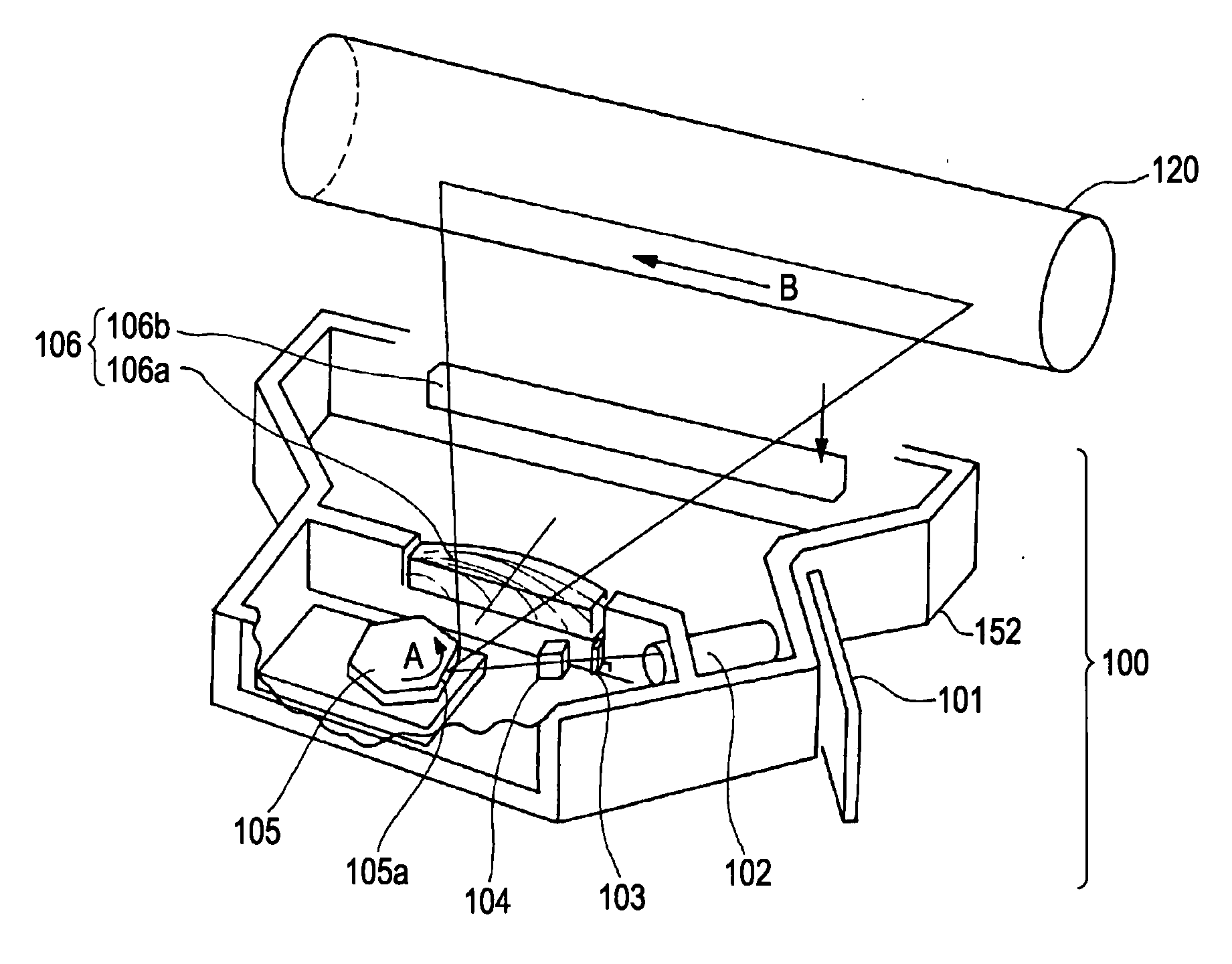
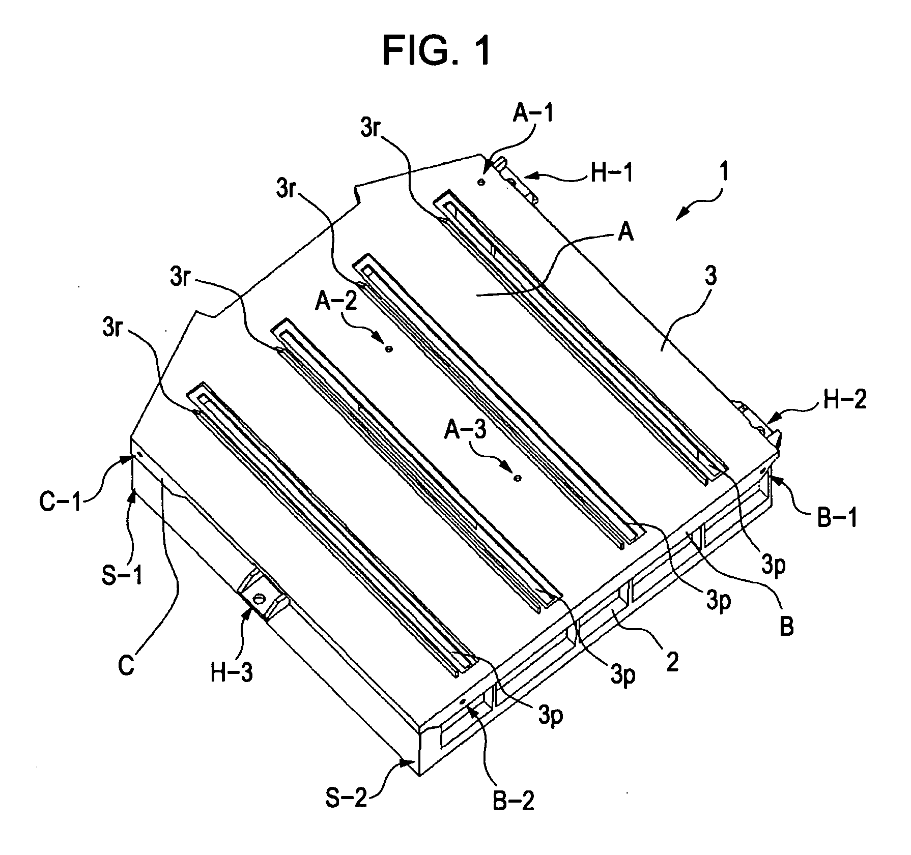
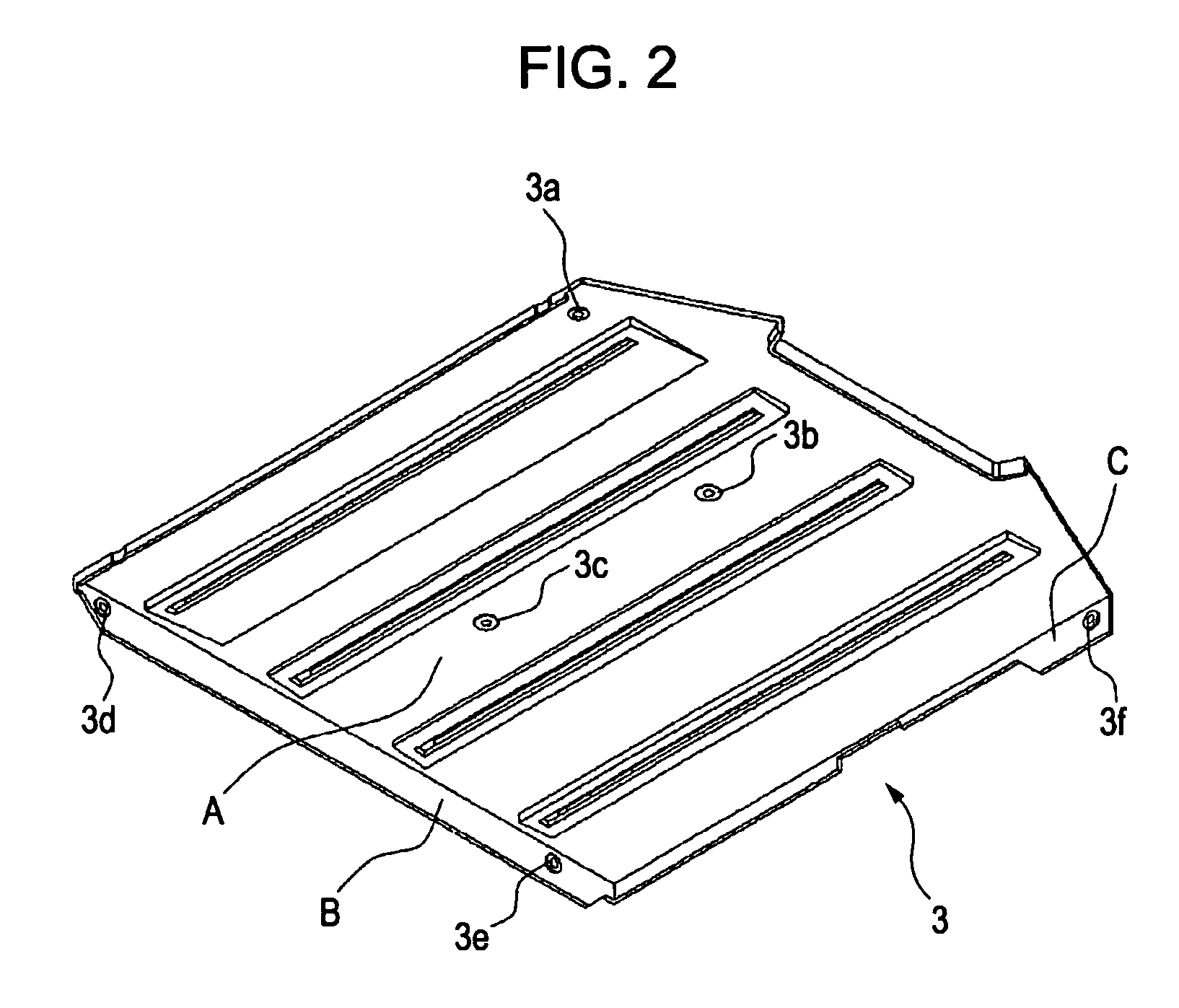
[0082] A first exemplary embodiment of the present invention will be described below with reference to the drawings. FIG. 1 is a perspective view of the scanning optical unit 1 according to the first exemplary embodiment. FIG. 2 is a perspective view of a cover according to the first exemplary embodiment. FIG. 3 is a perspective view of an optical box according to the first exemplary embodiment.

[0083] In FIG. 1, the scanning optical unit 1 is an optical unit detachably mounted to the image forming apparatus. The scanning optical unit 1 includes, as illustrated in FIGS. 2 and 3, an optical box 2 in the base body and a cover 3 covering an opening portion of the optical box 2. In this exemplary embodiment, the optical box 2 is a frame having an opening. The optical box 2 and the cover 3 are fastened together (e.g., in this non-limiting example at six fixed positions, i.e., fastened points A-1, A-2, A-3, B-1, B-2 and C-1), by using fixing members, (e.g., screws...

second exemplary embodiment

[0102]FIG. 5 is a perspective view for explaining fastened portions of an optical box in a scanning optical unit according to a second exemplary embodiment of the present invention. FIGS. 6A and 6B are each an enlarged view of the fastened portion in FIG. 5.

[0103] An optical box 11 in this second exemplary embodiment differs from the optical box 2 in the above-described first exemplary embodiment in shape of the fastened portions in the second plane B and the third plane C.

[0104] Fastened portions 11d, 11e and 11f are provided in the optical box 11. In each of those fastened portions, as illustrated in FIG. 6A, two partial cylindrical surfaces 11r are formed on both sides of a threaded hole 11s in which a fixing member, e.g., a screw, is engaged. Each of the partial cylindrical surfaces 11r has a center axis parallel to the first plane A and the second plane B or a center axis parallel to the first plane A and the third plane C. The fastened portions can be provided in the cover 1...


PUM


Abstract

At least one exemplary embodiment is directed to an optical unit adapted to irradiate image exposure light to an image carrier comprises a frame containing optical parts arranged therein and having an opening, and a cover adapted to cover the opening. The cover can be fixed by fixing members to the frame at three points in a first plane including the opening. The cover can further be fixed by fixing members to the frame at a second plane positioned on the frame and being adjacent to the first plane and at a third plane positioned on the frame and being not parallel to the second plane. Thus, an optical unit can be obtained which has high rigidity while, when the cover is attached to the opening, maintaining satisfactory flatness of the cover in a plane including the opening.

Description

BACKGROUND OF THE INVENTION [0001] 1. Field of the Invention [0002] The present invention relates to an optical unit for use in image forming apparatuses such as a laser beam printer and a digital copying machine. [0003] 2. Description of the Related Art [0004] Hitherto, a scanning optical unit has been used in image forming apparatuses such as a laser beam printer and a digital copying machine. One example of the image forming apparatuses will be described below with reference to FIG. 9. [0005]FIG. 9 is a schematic sectional view of a color image forming apparatus for recording image information in respective colors on a plurality of photoconductive drums and forming a color image by using a plurality of scanning optical units. [0006] The color image forming apparatus comprises four scanning optical units 100, four photoconductive drums 151-154, four development units 131-134, and four transfer units 121-124, the last threes corresponding to the four scanning optical units in one-t...

Claims


Application Information

Patent Timeline
IPC IPC(8): H04N1/00
CPCB41J2/471G02B26/12G03G15/04036G03G2215/0404G03G15/0435H04N1/12H04N2201/0082H04N2201/0446H04N1/1135
Inventor MAMIYA, TOSHIHARU
Owner CANON KK
Why Eureka
Try Eureka