

High-pressure Injection Proppant System
a proppant system and high-pressure technology, applied in the direction of fluid removal, drilling accessories, borehole/well accessories, etc., can solve the problems of difficult stimulation, difficult to stimulate, and the production of carbonic acid is extremely hard on the surfa
- Summary
- Abstract
- Description
- Claims
- Application Information
AI Technical Summary
Benefits of technology
Problems solved by technology
Method used
Image

Examples
first embodiment
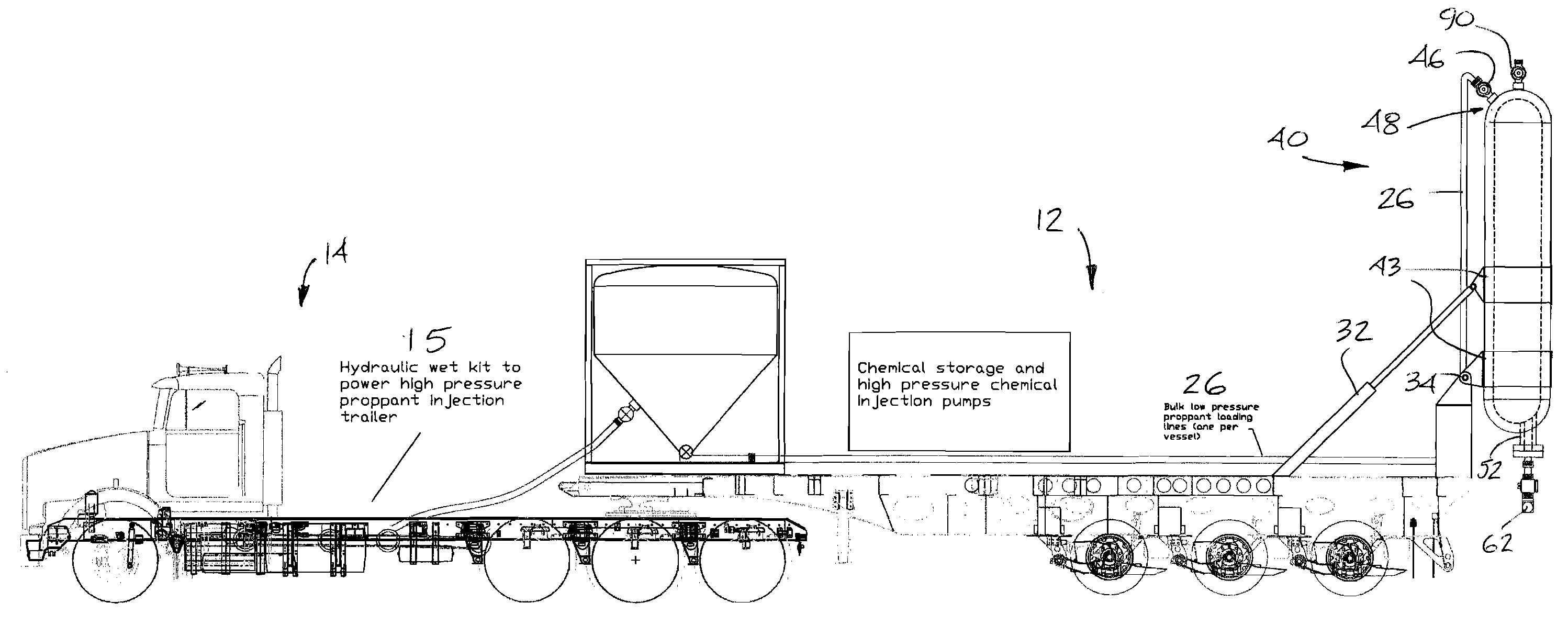
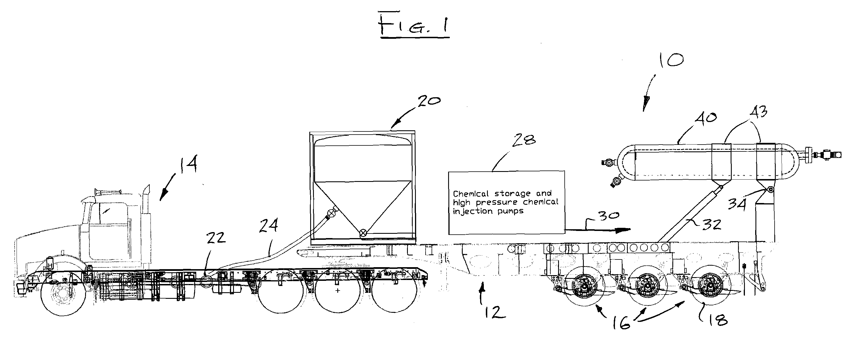
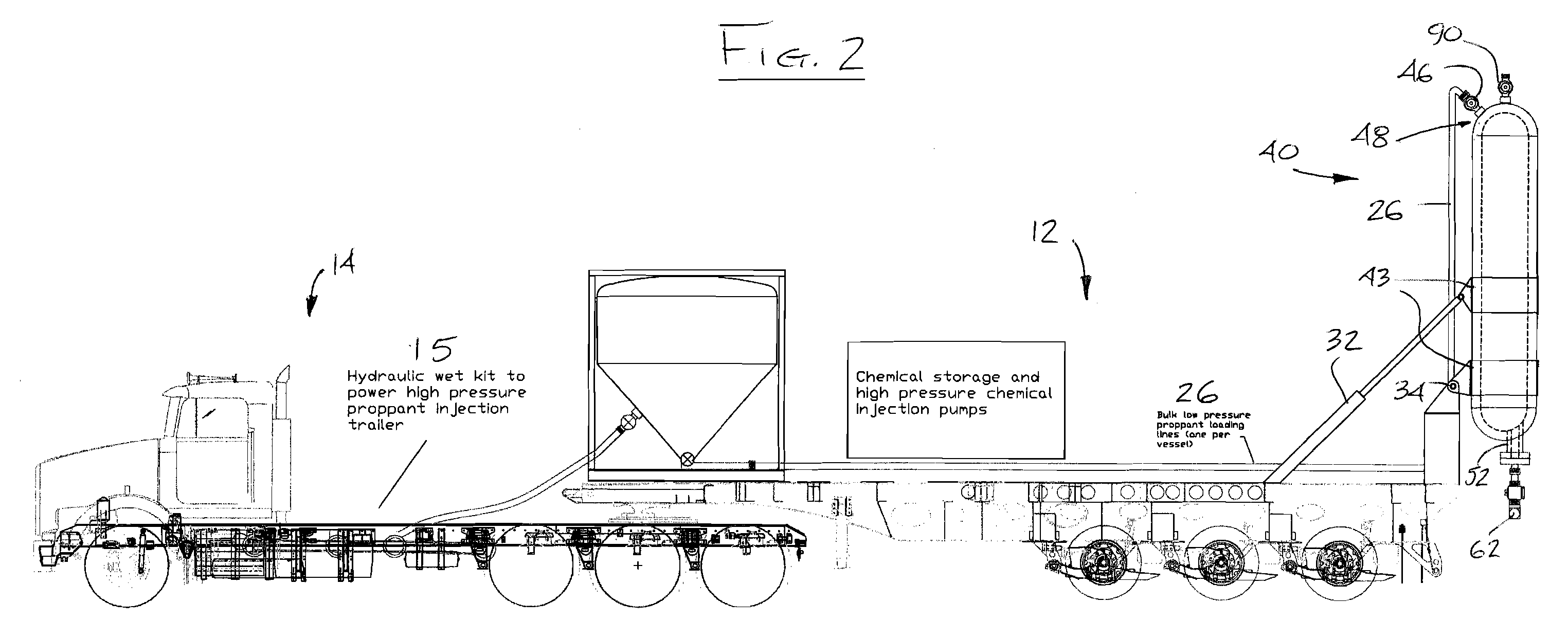
[0145] Reference is first made to FIGS. 1 to 3 which show a high-pressure injection proppant system, or “HIPS”, (generally designated by reference numeral 10) according to the present invention. The system is mounted on a carrier, which is preferably a wheeled trailer 12 adapted to be pulled by a motorized vehicle, or truck 14. It will be understood that the carrier may take various alternate forms, namely the trailer may itself be self-propelled, the truck and trailer may form one non-detachable unit, the system may be mounted on a skid for transport between sites, or the like. However, since the system is extremely heavy, not all carriers will be suitable for road transport as prescribed load limits for roads may be exceeded. Hence, in the present embodiment, the 24 wheeled trailer 12 is specifically designed to remain within such load limits (i.e. is “road legal”) by having three axles 16 with eight tires 18 per axle. Different axle and wheel combinations and quantities may be eq...
second embodiment
[0154] An alternate second embodiment of the present invention is shown in FIGS. 6 to 8 where the screws 154 are located longitudinally within the pressure vessels 140. The reference numerals used in these figures are similar to those used to describe the components of the system 10, with the addition of a prefix “1”. Each vessel has in essence three longitudinally aligned chambers. A first elongate chamber 144a is defined by the vessel's outer wall 142 for holding the proppent received through the first vessel inlet 146 via the delivery line 130. A pressure relief valve 190 bleeds excess pressure before filling the chamber 144a. A second elongate chamber 144b is longitudinally disposed within the first chamber 144a in a parallel relationship, and houses the screw 154 operated by the motor 158. The bottom end of the second chamber 144b has a first bottom opening 145 into the first chamber 144a to allow entry of the proppant. The screw raises the proppant to the opposed top end where...
fourth embodiment
[0177] A sample operating sequence of the fourth embodiment will now be set out, with reference to FIGS. 12-16 which show the vessel 340 and associated piping 360 in isolation from the trailer. The sequence is described for one pressure vessel, but is equally applicable to each vessel of a multi-vessel configuration:
[0178] Lower valves (such as the auger outlet valve 396) under the spherical pressure vessel are closed. The sand screw, or auger 354, is off (inoperative). The pressure vessel 340 is empty and unpressurized.
[0179] The top proppant supply and vent valves 346, 390 are opened and proppant is blown or pumped into the vessel until nearly full.
[0180] The top supply and vent valves 346, 390 (capped at 391) are closed.
[0181] The top fluid (nitrogen) valve 388 is opened and the pressure vessel is pressurized up to the line pressure of the main horizontal fluid line 361 running along the bottom of the trailer. In this embodiment the vessel has a pressure rating up to about 900...
PUM
 Abstract
Description
Claims
Application Information