Reinforcement ring

a technology of reinforcement rings and rings, applied in the field of reinforcement rings, can solve the problems of elements liable to deform under high pressure, and achieve the effect of preventing deformation or twisting of rings

Active Publication Date: 2006-12-28
INTERWELL NORWAY AS
View PDF2 Cites 21 Cited by
  • Summary
  • Abstract
  • Description
  • Claims
  • Application Information

AI Technical Summary

Benefits of technology

[0006] A reinforcement ring, includes an annular coil spring with a core unit arranged inside to prevent deforming or twisting of the ring under load. The core unit is formed fro

Problems solved by technology

Such elements have been liable to deform under high pressure, e.g.; the pressure existing at the en

Method used


Image

  • Reinforcement ring
  • Reinforcement ring
  • Reinforcement ring

Examples


Embodiment Construction

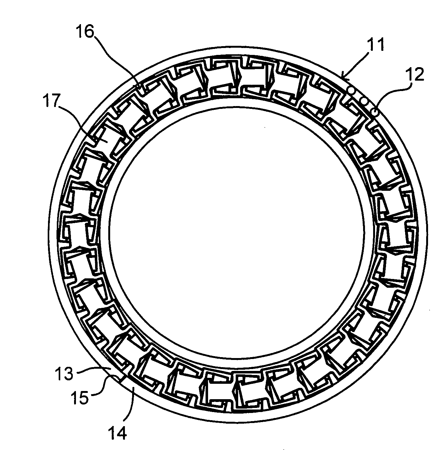
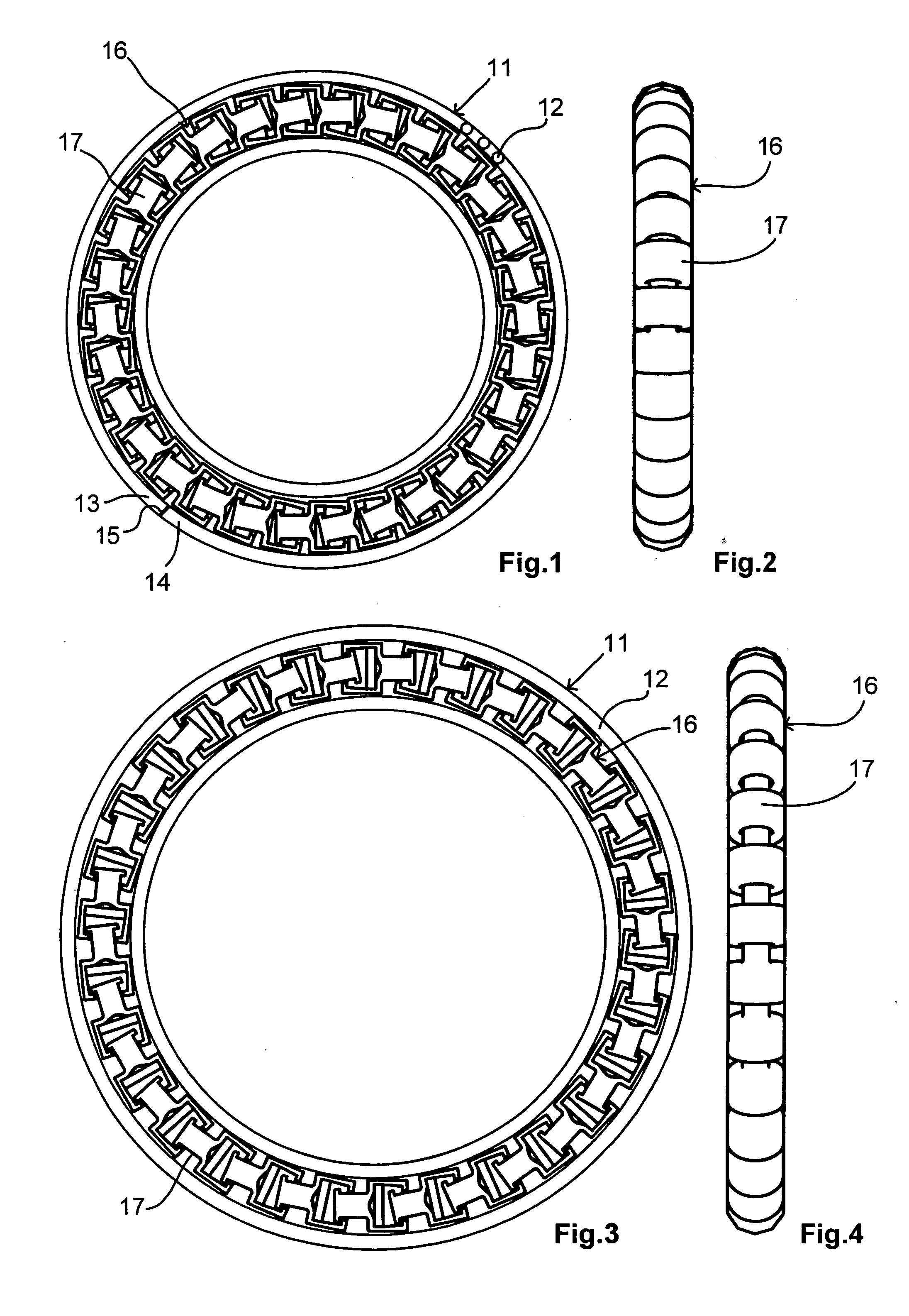
[0017]FIG. 1 shows a reinforcement ring 11 comprising an annular coil spring 12. The ends 13 and 14 of the coil spring 12 are joined before completion by soldering or gluing 15, as will be described below.

[0018] In the coil spring 12 a core unit 16 comprising a chain of core elements 17, are arranged, in the example 44 elements. The structure of the core elements 17 will be described in more detail with reference to FIGS. 5 and 6.

[0019]FIG. 2 shows the core unit 16 in its compressed form as used in the reinforcement ring in FIG. 1. Due to the function to be described below, the core elements 17 can be moved between a compressed position close to the adjoining core elements and an expanded position with a larger mutual distance.

[0020]FIGS. 3 and 4 show the reinforcement ring 11 and the core unit 16 in its expanded position.

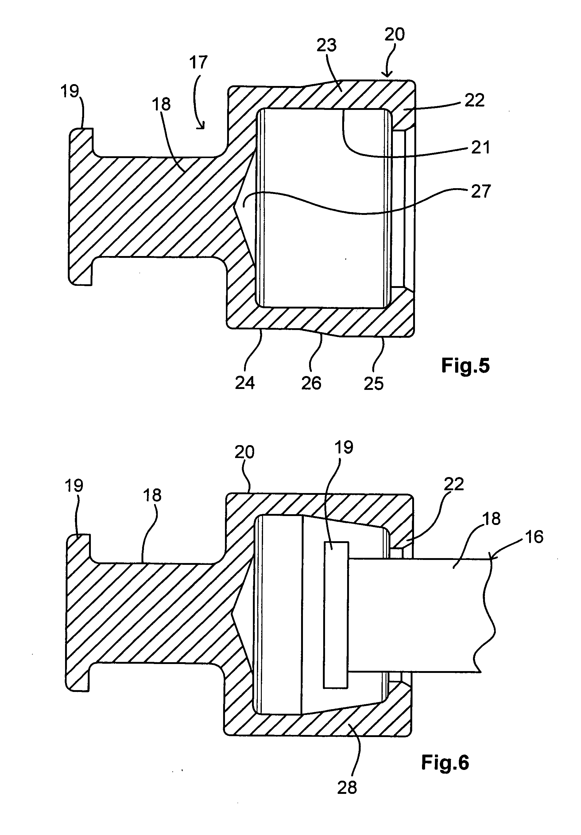
[0021]FIG. 5 shows a core element 17 in its pre-mounting form. The element 17 has a cylindrical shank 18 with a radial flange 19 at one end, and a cylindrical ...


PUM


Abstract

A reinforcement ring, includes an annular coil spring with a core unit arranged inside to prevent deforming or twisting of the ring under load. The core unit is formed from a chain of interlinked elements, each having a male part and a female part; the male parts of each element being engaged with corresponding female parts of an adjoining element.

Description

FIELD OF THE INVENTION [0001] The invention relates to a reinforcement ring, particularly for confining elastomeric sealing or packer elements in a well plug. BACKGROUND OF THE INVENTION [0002] Reinforcement rings are used for various purposes in packer elements, particularly to withstand high pressure and high temperatures. One common usage is to confine elastomeric packer or sealing elements in well bore plugs. [0003] Prior art reinforcement rings have been designed with two or more annular coil springs arranged concentric. Such elements have been liable to deform under high pressure, e.g.; the pressure existing at the ends of elastomeric sealing rings under high compacting pressure or at similar straining applications. [0004] An object of the invention is to provide a reinforcement ring enduring the stresses of heavy loads or pressures. Particularly, it is an object to provide a reinforcement ring withstanding the deforming forces acting at the high pressures of a well bore plug ...

Claims


Application Information

Patent Timeline
IPC IPC(8): E21B33/00E21BE21B33/12
CPCY10T428/215E21B33/1208E21B33/1216E21B33/12E21B33/127E21B33/1277
Inventor HIORTH, ESPEN
Owner INTERWELL NORWAY AS
Why Eureka
Try Eureka