High pressure lamp with lamp flicker suppression and lamp voltage control

a high-pressure lamp and lamp voltage control technology, which is applied in the direction of electric variable regulation, process and machine control, instruments, etc., can solve the problems of unstable discharge arc from the cathode electrode to the anode electrode, known problems of lamp flicker, etc., to achieve further stabilization of the electrode tip, reduce flicker, and reduce flicker.

Inactive Publication Date: 2006-12-28
GENERAL ELECTRIC CO
View PDF14 Cites 22 Cited by
  • Summary
  • Abstract
  • Description
  • Claims
  • Application Information

AI Technical Summary

Benefits of technology

[0004] Provided is a system and method of operating a high pressure discharge lamp to significantly reduce flicker by selecting an optimal Rt and Ri for a lamp current supplying a high pressure lamp. In addition, an apparatus and method are provided to reduce flicker by combining one or more current pulses with an alternating lamp current such that the leading edge of the current pulse occurs substantially simultaneously with or after a time delay Td from the trailing edge of a half cycle of the alternating lamp current, i.e., the current pulse is not superimposed on the later part of a half cycle of the alternating lamp current.
[0005] Also provided is a method of controlling the size of the electrode tip diameter, electrode tip protrusion length and electrode tip growth rate by controlling the current ratio Ri and duration ratio Rt of the alternating lamp current supplying a high pressure lamp. By controlling the current ratio Ri and duration ratio Rt of the alternating lamp current, the electrode tip protrusion size and electrode tip growth rate can be controlled to provide further stabilization of the electrode tip and further reduce flicker.

Problems solved by technology

Lamp flicker is a known problem in high pressure lamps, such as video projection lamps.
Often, a discharge arc from the cathode electrode to the anode electrode is not stable because the origin of the discharge arc is not stable.

Method used


Image

  • High pressure lamp with lamp flicker suppression and lamp voltage control
  • High pressure lamp with lamp flicker suppression and lamp voltage control
  • High pressure lamp with lamp flicker suppression and lamp voltage control

Examples


Embodiment Construction

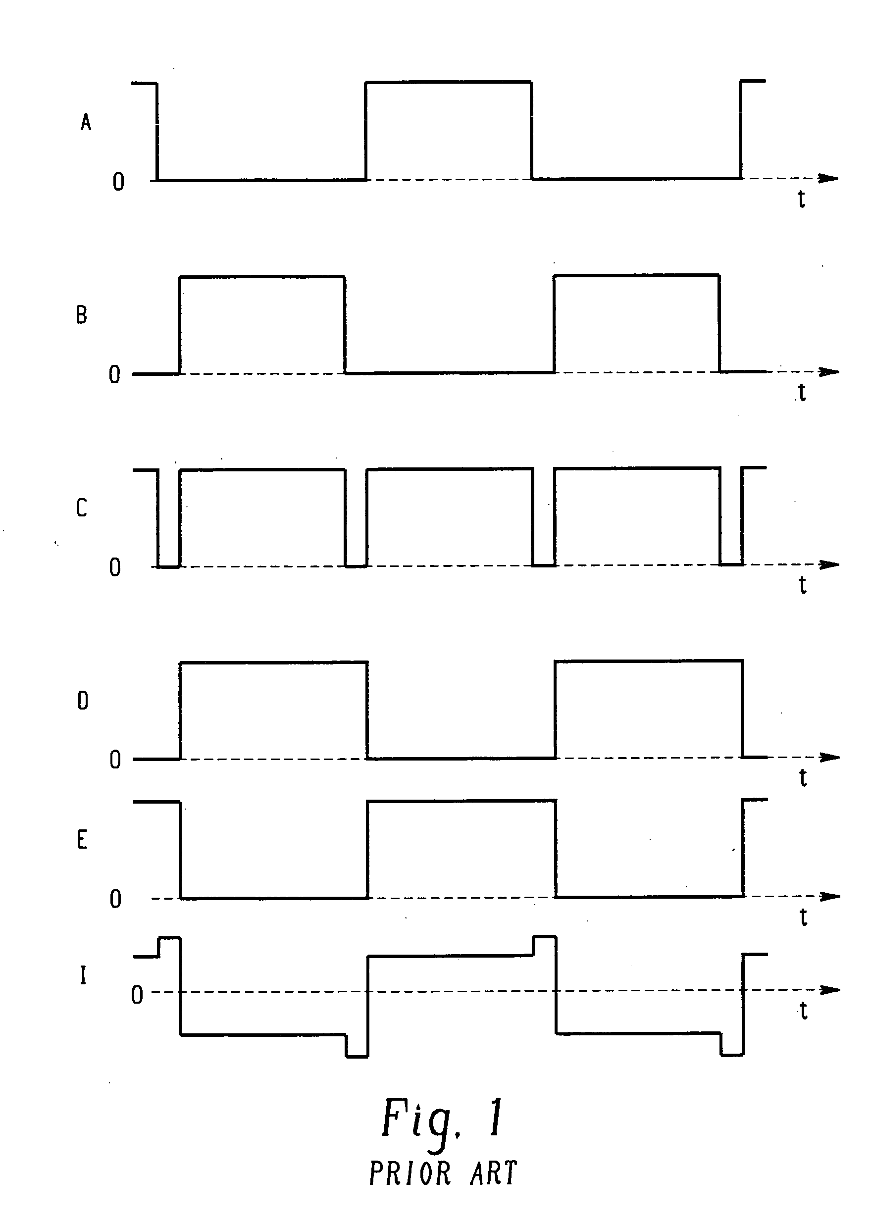
[0024]FIG. 1 shows the prior art arrangement of Derra, et al. —U.S. Pat. No. 5,608,294. As briefly noted above, the Derra patent discloses a method of operating and a circuit arrangement for suppressing flickering in a high pressure discharge lamp. A current pulse is generated in a fraction of the half period or cycle of the lamp current. The current pulse has the same polarity as the lamp current and is superimposed in the latter pat of the half cycle. In this manner, the total amount of current flowing through the lamp is increased, and likewise the temperature of the lamp electrode is increased. The increased temperature raises the stability of the discharge arc and as a result, the arc originates from the same place on the electrode.

[0025] However, as noted above, Derra identifies selected limits to operating ranges. Specifically, Derra limits Ri to the range of 0.6 to 2.0 and Rt in the range of 0.05 to 0.15. There are still other ranges of effective operation outside of those ...


PUM


Abstract

A method and system to supply current to a high pressure lamp is provided, the method and system comprising an alternating lamp current waveform with a half cycle mean amplitude I1 and a half cycle time duration T, a current pulse waveform including at least one current pulse with a half cycle mean amplitude I2 and at least one current pulse occurring after the trailing edge of a half cycle of the alternating lamp current, the pulse having a half cycle duration of Tp. These waveforms are combined to generate a current waveform including a current pulse waveform, the current pulse waveform starting after a time delay Td from the trailing edge of a half cycle of the alternating lamp current waveform, the time duration Tp of the at least one current pulse lasting less than the remaining time before the leading edge of the second half cycle of the alternating lamp current waveform. The combined current waveform supplies current to a high pressure lamp and produces a cone shaped tip protrusion which reduces lamp flicker.

Description

BACKGROUND [0001] Lamp flicker is a known problem in high pressure lamps, such as video projection lamps. It is critical to reduce the flicker in order to achieve high performance in projection lamp applications. The following relates to operating a high pressure lamp to reduce flicker. [0002] Lamp flicker in a high pressure lamp is associated with the temperature and physical characteristics of the electrode tip protrusions. Often, a discharge arc from the cathode electrode to the anode electrode is not stable because the origin of the discharge arc is not stable. An electrode that is too cold or hot will produce micro spikes resulting from the electrode discharge arc jumping from one spot on the electrode to a different spot on the electrode. This is perceived by a viewer as flicker. U.S. Pat. No. 5,608,294 (hereafter referred to as Derra et al.) proposes one solution to this problem and discusses the reasons for flicker understood by one of skill in the art of high pressure lamps...

Claims


Application Information

Patent Timeline
Patent Type & Authority Applications(United States)
IPC IPC(8): G05F1/00
CPCY02B20/202H05B41/3928Y02B20/00Y10S315/07
Inventor LI, JIANWUCHALMERS, ALAN G.VARGA, VIKTOR K.GURIN, TIMOTHY B.ALLEN, GARY R.KOTKUNDE, ANJALIMCNAMARA, JAMES C.
Owner GENERAL ELECTRIC CO
Why Eureka
Try Eureka