Method and apparatus for implementing level of detail with ray tracing

a technology of detail and ray tracing, applied in the field of computer graphics, can solve the problems of affecting the visibility of various overlapping objects, and introducing additional problems

Inactive Publication Date: 2006-12-28
CLOUDROCK LLC
View PDF8 Cites 19 Cited by
  • Summary
  • Abstract
  • Description
  • Claims
  • Application Information

AI Technical Summary

Benefits of technology

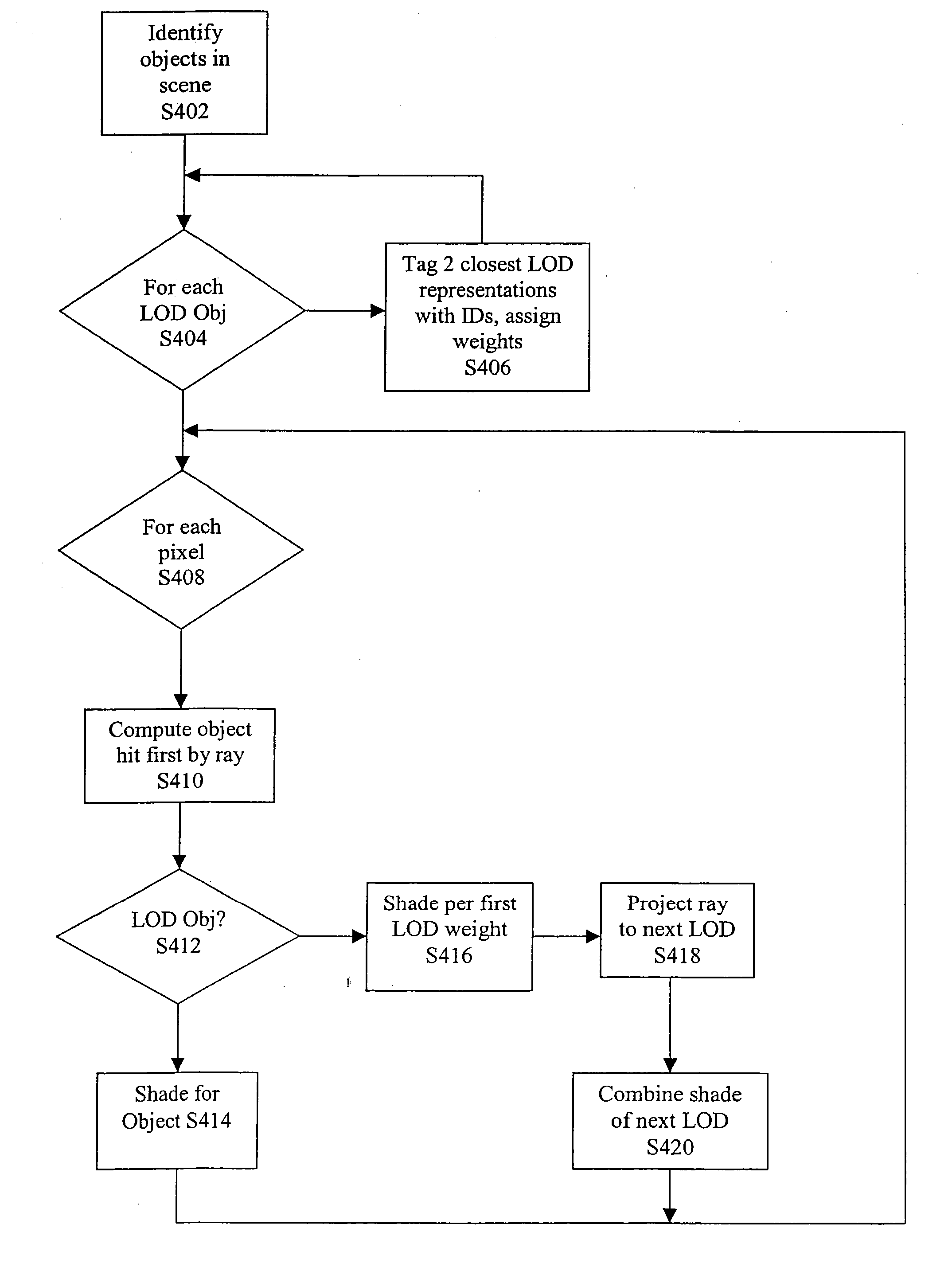
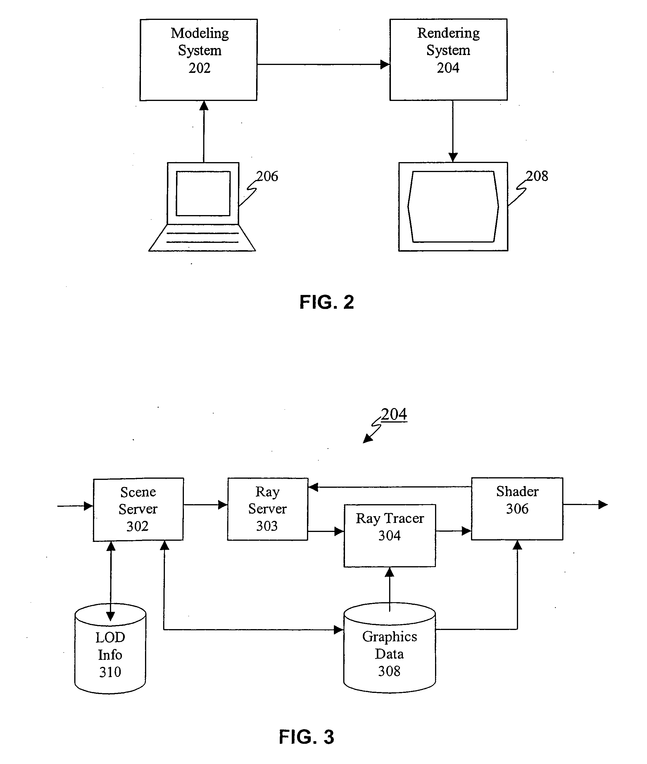
[0005] The present invention relates to computer graphics applications involving scene rendering using objects modeled at multiple levels of detail. In accordance with an aspect of the invention, a ray tracer implementation allows users to specify multiple versions of a particular object, categorized by LOD ID's. A scene server selects the version appropriate for the particular scene, based on the perceived size of the object on the screen for example, and provides a smooth transition between multiple versions of an object model. In one example, the scene server will select two LOD representations associated with a given object and assign relative weights to each representation. The LOD weights are specified to indicate how to blend these representations together. A ray tracer computes the objects hit by camera rays associated with pixels in the camera window, as well as secondary rays in recursive implementations, and rays striking LOD objects are detected and shaded in accordance with the weights assigned to the different representations. Embodiments are disclosed for level of detail control using both forward ray tracing and backward ray tracing, including handling of camera rays, reflected rays, refracted rays and shadow rays.

Problems solved by technology

However, a problem arises in that different LODs may affect the visibility of various overlapping objects.
Further, for certain types of object visibility determinations such as ray tracing, additional problems are encountered that have not been addressed in the prior art, such as how to account for child rays (e.g. shadow, refracted and reflected rays) spawned from an object having different LODs.

Method used


Image

  • Method and apparatus for implementing level of detail with ray tracing
  • Method and apparatus for implementing level of detail with ray tracing
  • Method and apparatus for implementing level of detail with ray tracing

Examples


Embodiment Construction

[0015] The present invention will now be described in detail with reference to the drawings, which are provided as illustrative examples of the invention so as to enable those skilled in the art to practice the invention. Notably, those skilled in the art will recognize that various components can be implemented using various combinations of hardware, software and / or firmware, and the figures and examples below are not meant to limit the scope of the present invention. Moreover, where certain elements of the present invention can be partially or fully implemented using known components, only those portions of such known components that are necessary for an understanding of the present invention will be described, and detailed descriptions of other portions of such known components will be omitted so as not to obscure the invention. Further, the present invention encompasses present and future known equivalents to the known components referred to herein by way of illustration.

[0016]...


PUM


Abstract

The present invention relates to computer graphics applications involving scene rendering using objects modeled at multiple levels of detail. In accordance with an aspect of the invention, a ray tracer implementation allows users to specify multiple versions of a particular object, categorized by LOD ID's. A scene server selects the version appropriate for the particular scene, based on the size of the object on the screen for example, and provides a smooth transition between multiple versions of an object model. In one example, the scene server will select two LOD representations associated with a given object and assign relative weights to each representation. The LOD weights are specified to indicate how to blend these representations together. A ray tracer computes the objects hit by camera rays associated with pixels in the camera window, as well as secondary rays in recursive implementations, and rays striking LOD objects are detected and shaded in accordance with the weights assigned to the different representations. Embodiments are disclosed for level of detail control using both forward ray tracing and backward ray tracing, including handling of camera rays, reflected rays, refracted rays and shadow rays.

Description

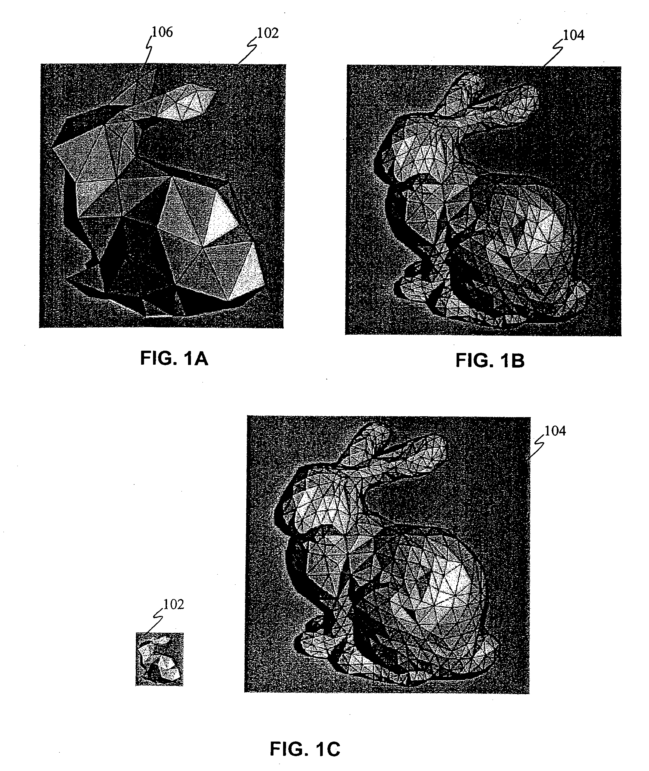
FIELD OF THE INVENTION [0001] The present invention relates generally to computer graphics, and more particularly, to rendering of scenes with objects having multiple levels of detail using techniques such as ray tracing. BACKGROUND OF THE INVENTION [0002] Object modeling and rendering are performed in many computer graphics applications such as CAD / CAM, computer animation and gaming, visualization systems, flight simulators, special effects, medical imaging, architectural visualization, virtual reality, etc. [0003] In some applications, multiple level of detail (LOD) models of objects (typically 3-dimensional, but can be 2-dimensional) can be specified to satisfy various shot requirements. FIG. 1A illustrates a relatively un-detailed model 102 consisting of relatively few geometric primitives (e.g. polygons or triangles 106) while FIG. 1B illustrates a very detailed model 104 of the same object consisting of relatively many geometric primitives. The selection of which model 102, 10...

Claims


Application Information

Patent Timeline
Patent Type & Authority Applications(United States)
IPC IPC(8): G06T17/00
CPCG06T15/06G06T2210/36G06T15/40
Inventor MUNSHI, AAFTAB A.WOOD-PATRICK, MARK
Owner CLOUDROCK LLC
Why Eureka
Try Eureka