Ink tank holder and ink jet printing head cartridge

Inactive Publication Date: 2006-12-28
CANON KK
View PDF7 Cites 35 Cited by
  • Summary
  • Abstract
  • Description
  • Claims
  • Application Information

AI Technical Summary

Benefits of technology

[0021] According to the present invention, the display function is separated from the light emitting portion disposed on the ink tank and the light guiding portion is provided on the ink tank holder in order to establish optical connection between the light emitting portion and a display section. In this way, it is possible to achieve a configuration to dispose the light emitting portion and the display section respectively in the optimum locations at low costs without a requirement of wiring used for electric supply and signal transmitting,

Problems solved by technology

Therefore, the light emitting portion such as the LED, the operating members for fitting the ink tank, and the electrical contacts may restrict the layout freedom with one another.
As a result, these members are not always disposed in the optimum locations.
Therefor, there is a problem in that the degree of arrangement freedom of each of the LED and the electric connecting part is restricted.
While it is thought to provide a large-sized PCB for covering both preferable positions for the electric connecting part and the LED, the production cost rises therefor.
When the structure disclosed in Japanese Patent Application Laid-open No. 4-275156 (1992) is applied to the printer capable of mounting a plurality of independent ink tanks for the respective colors, a structure for mounting the ink tanks onto the printer is limited.
However, the conductor wires in correspondence to the number of the ink alarming lamps are necessary, which complicates the wiring arrangement not only to cause the production cost to rise but also to deteriorate the visibility of the lamps by the conductor wires or the connection thereof.
In this case, ho

Method used


Image

  • Ink tank holder and ink jet printing head cartridge
  • Ink tank holder and ink jet printing head cartridge
  • Ink tank holder and ink jet printing head cartridge

Examples


Embodiment Construction

[0054] The present invention will be described below in more detail, with reference to the attached drawings illustrating the preferred embodiments.

1. Mechanical Structures

1.1 Embodiments of an Ink Tank and a Tank Holder (FIG. 1A to FIG. 6B)

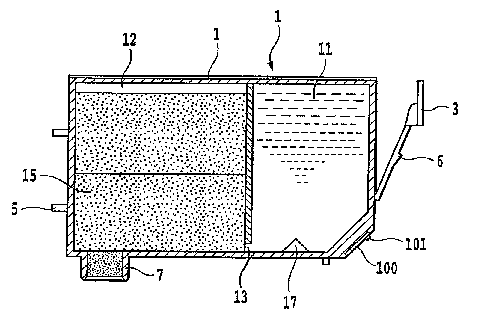
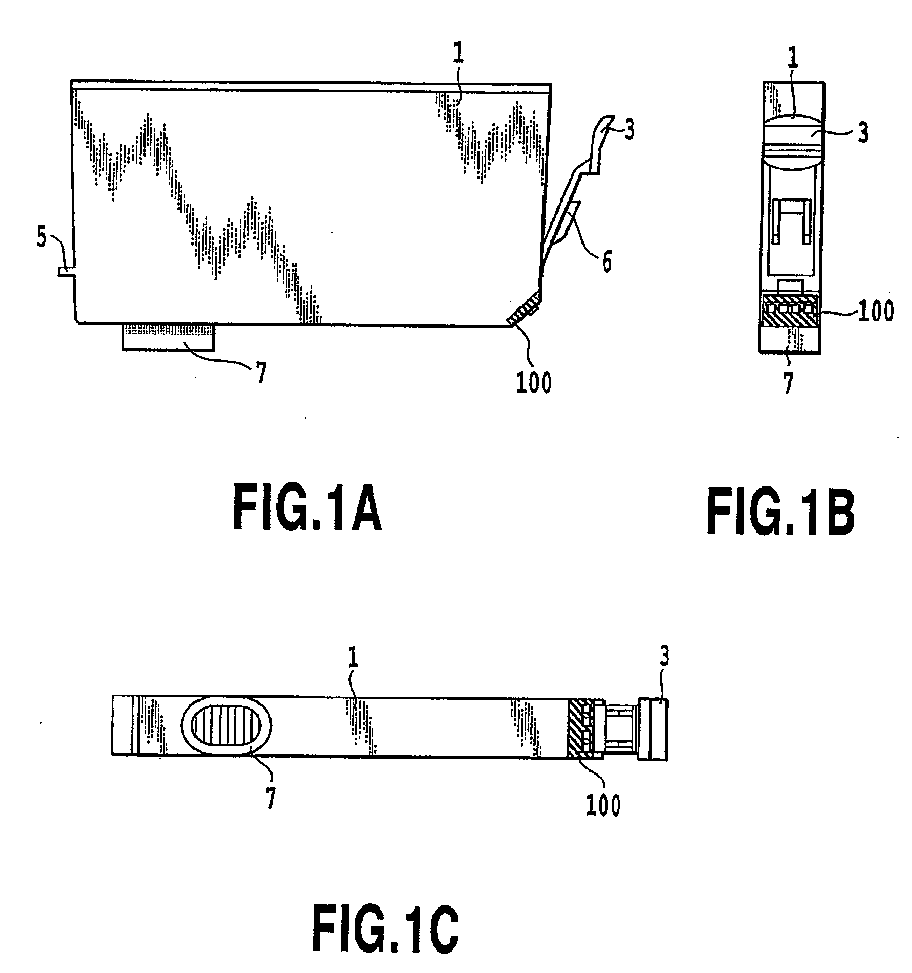
[0055]FIGS. 1A, 1B and 1C are a side view, a front view and a bottom view, respectively, of an ink tank which is a liquid container according to a first embodiment of the present invention. In this regard, in the following description, a front surface of the ink tank is a surface opposed to the user, from which the manipulation of the ink tank such as an attachment / detachment thereof and the transmission of information to the user (the projecting of light from a display section described later) are possible.

[0056] In FIGS. 1A to 1C, the ink tank 1 according to this embodiment has a supporting member 3 supported in a lower portion of the front surface. The supporting member 3 is formed of resin to be integral with an outer casing of the ink ...


PUM


Abstract

In a configuration to inform conditions of an ink tank such as an ink residual quantity by use of a light emitting portion such as a light emitting diode, a display in a position easily viewable to a user is achieved without requiring electric wiring that hinders user visibility and operability. A display section for displaying information by letting light out is separated from a light emitting portion, and a light guiding portion for achieving optical connection between both of the constituents is provided on an ink tank holder. In this way, it is possible to dispose the light emitting portion and the display section respectively in optimum locations, and to ensure freedom of disposing the display section in a position achieving fine user visibility.

Description

BACKGROUND OF THE INVENTION [0001] 1. Field of the Invention [0002] The present invention relates to an ink tank holder for detachably supporting an ink tank having a configuration to inform its own conditions such as an ink residual quantity used in ink jet printing by means of light emission of an indicator such as a light emitting diode (LED). The present invention also relates to an ink tank which is attachable to and detachable from the ink tank holder, and to an ink jet printing head cartridge provided with the ink tank holder. [0003] 1. Description of the Related Art [0004] In recent years, print applications while connecting a digital camera directly to a printer as a printing apparatus without use of a personal computer (PC) are increasing along with spread of digital cameras. Moreover, print applications configured to perform data transfer by attaching a card-type information storage medium, which serves as an information storage medium detachable from a digital camera, di...

Claims


Application Information

Patent Timeline
IPC IPC(8): B41J2/195
CPCB41J2/17513B41J2/17566B41J2/17546B41J2/1752
Inventor KITAGAWA, TAKATOSHIHATASA, NOBUYUKI
Owner CANON KK
Why Eureka
Try Eureka