Addressable irradiation of images

a mark-based, image-based technology, applied in the direction of electrographic process equipment, printing, instruments, etc., can solve the problems of ink smear or transfer, slow drying time can be an even larger obstacle to high print speed, and the drying time is therefore an obstacle to high speed printing, so as to achieve high overall output, improve productivity, and improve the effect of reliability

Active Publication Date: 2006-12-28
XEROX CORP
View PDF99 Cites 84 Cited by
  • Summary
  • Abstract
  • Description
  • Claims
  • Application Information

AI Technical Summary

Problems solved by technology

If printed pages are stacked without sufficient drying time, ink may smear or transfer to the adjacent sheet.
Drying time is therefore an obstacle to high speed printing.
In applications where double-side printing is used, or where printing is performed on non-absorbent substrates, the slow dry time can be an even larger obstacle to high print speeds.
Fusers, because of the high temperatures at which they operate and frequent heating and cooling cycles that they undergo, tend to be prone to failure or suffer reliability issues.
The reliability issues are of particular concern in printing systems which employ several small marking devices.
However, since each marking device in the printing system has its own dedicated fuser, the reliability issues are compounded.
These methods for fusing and curing images all involve exposing the entire sheet to the energy source, which is both energy consuming and generates excess energy to be dissipated by the fusing system and may also cause sheet shrinkage and or curl.

Method used


Image

  • Addressable irradiation of images
  • Addressable irradiation of images
  • Addressable irradiation of images

Examples


Embodiment Construction

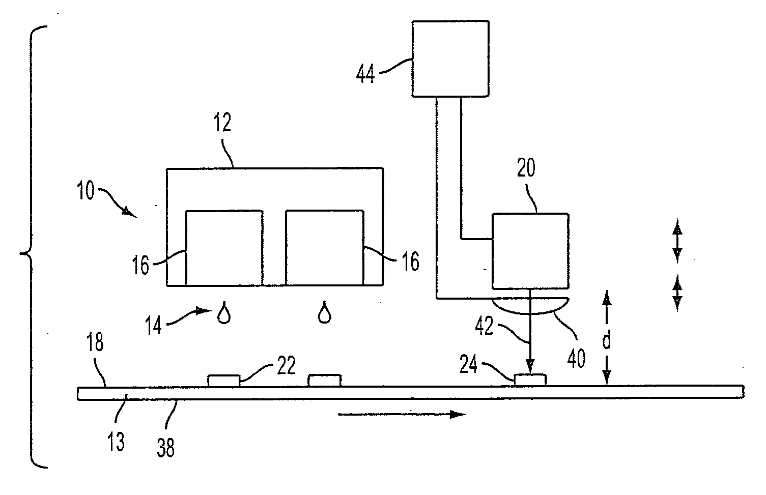
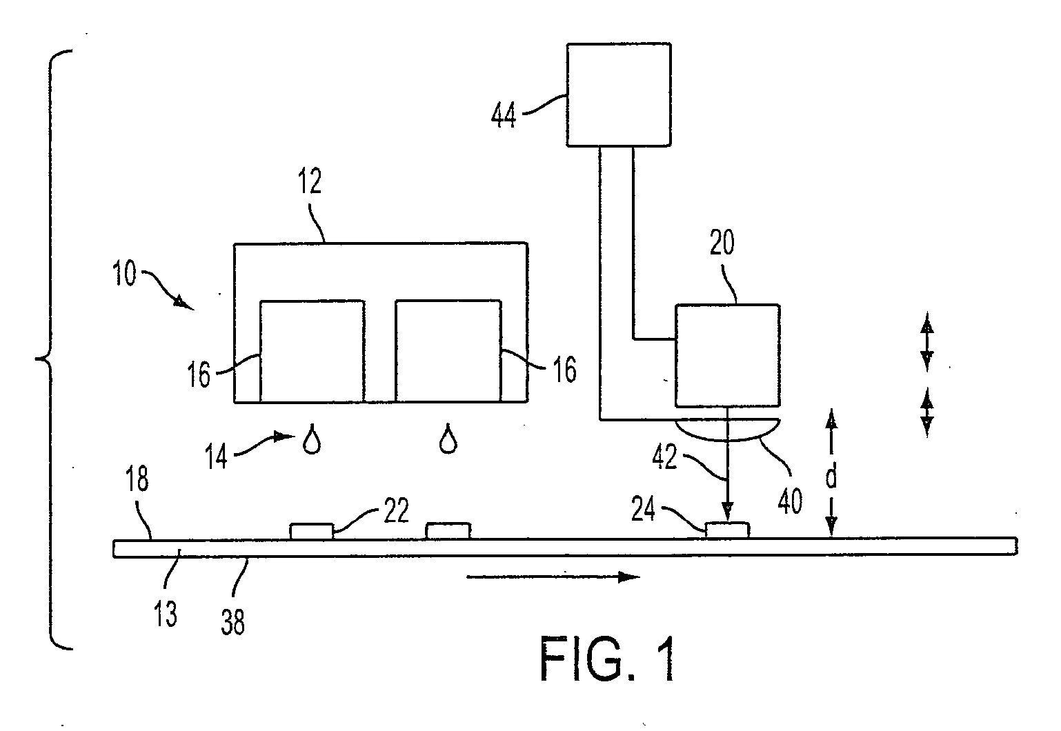
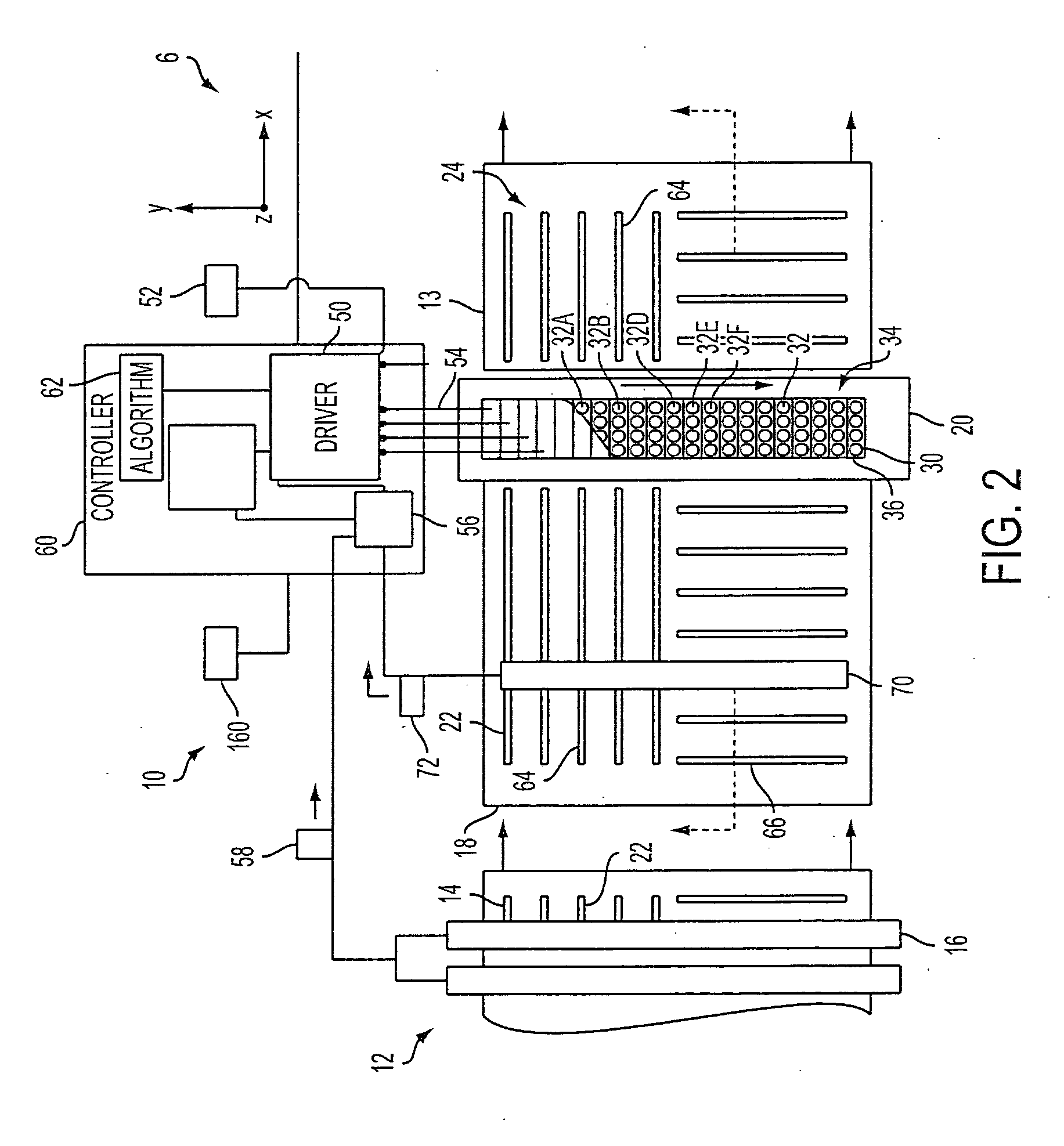
[0032] Aspects of the exemplary embodiment relate to a marking system comprising at least one marking device which applies a marking material to a substrate, such as print media, the marking material comprising a radiation-sensitive material which reacts upon exposure to radiation within a range of wavelengths and an irradiation device which irradiates the substrate with radiation within the range of wavelengths, the irradiation device including an array of selectively addressable irradiation elements.

[0033] The marking system may be a printing system, such as a xerographic system in which dry toner is applied to a substrate, or an ink-jet, gravure, or offset system, in which a liquid marking material is applied to the substrate. In both liquid ink systems and solid toner systems, the marking material forms an image on the substrate. The marking system may include one or a plurality of marking devices, such as one, two, three, four, six, eight, or more marking devices. In various a...


PUM


Abstract

A marking system includes at least one image applying component for applying a marking material to a substrate in forming an image on the substrate. The marking material includes a radiation sensitive material. An addressable irradiation device receives the marked substrate from the image applying component. The irradiation device provides an array of addressable irradiation elements which irradiate the marked substrate. At least some of the irradiation elements are selectively actuable. The irradiation device emits radiation within a range of wavelengths to which the radiation sensitive material is sensitive.

Description

CROSS REFERENCE TO RELATED APPLICATIONS [0001] The following co-pending applications, the disclosures of which are incorporated herein in their entireties, by reference, are mentioned: [0002] U.S. Provisional Application Ser. No. 60 / 631,651 (Attorney Docket No. 20031830-US-PSP), filed Nov. 30, 2004, entitled “TIGHTLY INTEGRATED PARALLEL PRINTING ARCHITECTURE MAKING USE OF COMBINED COLOR AND MONOCHROME ENGINES,” by David G. Anderson, et al.; [0003] U.S. Provisional Patent Application Ser. No. 60 / 631,918 (Attorney Docket No. 20031867-US-PSP), filed Nov. 30, 2004, entitled “PRINTING SYSTEM WITH MULTIPLE OPERATIONS FOR FINAL APPEARANCE AND PERMANENCE,” by David G. Anderson et al.; [0004] U.S. Provisional Patent Application Ser. No. 60 / 631,921 (Attorney Docket No. 20031867Q-US-PSP), filed Nov. 30, 2004, entitled “PRINTING SYSTEM WITH MULTIPLE OPERATIONS FOR FINAL APPEARANCE AND PERMANENCE,” by David G. Anderson et al.; [0005] U.S. application Ser. No. 10 / 999,450 (Attorney Docket No. 2004...

Claims


Application Information

Patent Timeline
Patent Type & Authority Applications(United States)
IPC IPC(8): B41J2/01G03G15/20
CPCG03G15/2007B41J11/002B41M7/0081B41J11/00212B41J11/00214G03G15/2098
Inventor GERMAN, KRISTINE A.LOFTHUS, ROBERT M.
Owner XEROX CORP
Why Eureka
Try Eureka