Magnetic disk apparatus

Inactive Publication Date: 2006-12-28
FUJITSU LTD
View PDF5 Cites 8 Cited by
  • Summary
  • Abstract
  • Description
  • Claims
  • Application Information

AI Technical Summary

Benefits of technology

[0011] Accordingly, it is a general object of the present invention to provide a novel and usef

Problems solved by technology

Thus, if the contact area is reduced too much or the gap is formed, dust or low-molecular organic gas contained in outside air may come into the inside of the apparatus from the outside.
In addition, in a case where a particle diameter of the dust is substantially the same as the flying height, if the dust goes in between the magnetic head and the magnetic

Method used


Image

  • Magnetic disk apparatus
  • Magnetic disk apparatus
  • Magnetic disk apparatus

Examples


first embodiment

[0036]FIG. 5 is an exploded perspective view of a magnetic disk apparatus of a first embodiment of the present invention. FIG. 6 is a cross-sectional view taken along a line A-A of FIG. 5. The line A-A passes through a substantially center part of a spindle motor and is along a diameter direction of a magnetic disk.

[0037] Referring to FIG. 5 and FIG. 6, a magnetic disk apparatus 10 of the first embodiment includes a housing 11, a recording and reproducing part, a cover part 15, and others. The recording and reproducing part includes a magnetic disk 12 provided on the housing 11, a magnetic head13, an actuator unit 14, and others. An opening part of the magnetic disk 12 is fitted around a rotational shaft 17. The magnetic disk 12 is fixed to a hub 16 from an upper side. The magnetic disk 12 is rotated by a spindle motor 18.

[0038] A base part of the magnetic head 13 is attached to an arm 19. The magnetic head 13 is provided to the actuator unit 14 via the arm 19. The magnetic head 1...

second embodiment

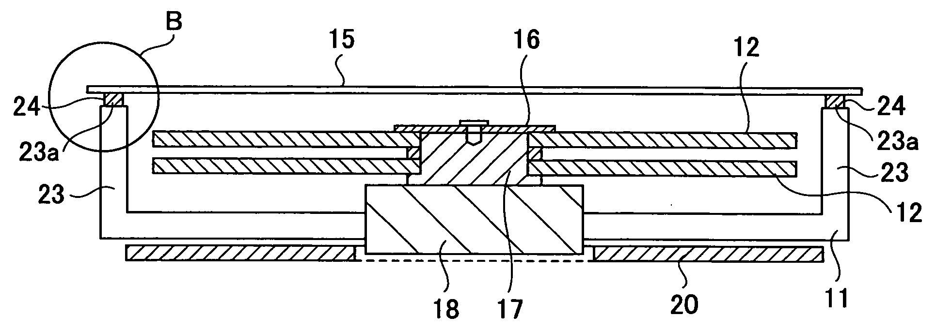
[0064]FIG. 10 is an exploded perspective view of a magnetic disk apparatus of a second embodiment of the present invention. FIG. 11 is a cross-sectional view taken along a line C-C of FIG. 10. FIG. 12 is an enlarged view of a part D of FIG. 11. In FIG. 10 through FIG. 12, parts that are the same as the parts discussed above are given the same reference numerals, and explanation thereof is omitted.

[0065] Referring to FIG. 10 through FIG. 12, in a magnetic disk apparatus 40 of the second embodiment, a housing 41 has a plate-shaped configuration and a circumference edge part 43 of the cover body 42 has a convex shape. Other than that the packing 44 is fixed to the adhesive surface 43a of the circumference edge part 43, the magnetic disk apparatus 40 has the same structure as the structure of the magnetic disk apparatus of the first embodiment.

[0066] The housing 41 has a plate-shape configuration. The magnetic disk 12, the magnetic head 13, and the actuator unit 14 are provided on a s...


PUM


Abstract

A magnetic disk apparatus includes a base body of which one surface is opened, a cover part covering the opened surface of the base body, and a recording and reproducing part provided on the base body and having a magnetic disk and a magnetic head received in a space formed between the base body and the cover part. A convex part is provided along a perimeter of a circumference edge part of one of the base body and the cover part. A first surface of the convex part faces a second flat surface. A packing for sealing is fixed to the first surface of the convex part so as to come in contact with the second flat surface.

Description

BACKGROUND OF THE INVENTION [0001] 1. Field of the Invention [0002] The present invention generally relates to magnetic disk apparatuses, and more specifically a magnetic disk apparatus having a structure having good sealability (the structure is sealable). [0003] 2. Description of the Related Art [0004] These days, a magnetic disk apparatus is used not only as an auxiliary storage apparatus of a computer but also for a portable terminal apparatus or a video apparatus. As demand for using the magnetic disk apparatus is expanded, high capacity and miniaturization of the magnetic disk apparatus are required. [0005]FIG. 1 is an exploded perspective view of a related art magnetic disk apparatus. As shown in FIG. 1, the magnetic disk apparatus 100 includes a housing 101. A magnetic disk 102, a magnetic head 103, and an actuator 104 are provided on an upper surface of the housing 101. An electronic substrate (not shown in FIG. 1) for controlling the magnetic disk apparatus is provided on ...

Claims


Application Information

Patent Timeline
IPC IPC(8): G11B33/14
CPCG11B17/038G11B33/1466G11B33/12
Inventor INOUE, HITOSHISHIKANO, KAZUNORI
Owner FUJITSU LTD
Why Eureka
Try Eureka