Unlock instant, AI-driven research and patent intelligence for your innovation.

Zoom optical system

Inactive Publication Date: 2006-12-28
CANON KK
View PDF3 Cites 3 Cited by
  • Summary
  • Abstract
  • Description
  • Claims
  • Application Information

AI Technical Summary

Problems solved by technology

In U.S. Pat. No. 3,305,294 and U.S. Pat. No. 3,583,790, a method is described for changing the power and correcting the aberration using a pair of rotationally asymmetric lenses; however, the image plane cannot be maintained constant when the power is changed.
H02-119103, a principle is described for changing the power while maintaining the image pane constant; however, it has not yet led to a practical design for obtaining excellent images by correcting or reducing the aberration.

Method used


Image

  • Zoom optical system
  • Zoom optical system
  • Zoom optical system

Examples


first exemplary embodiment

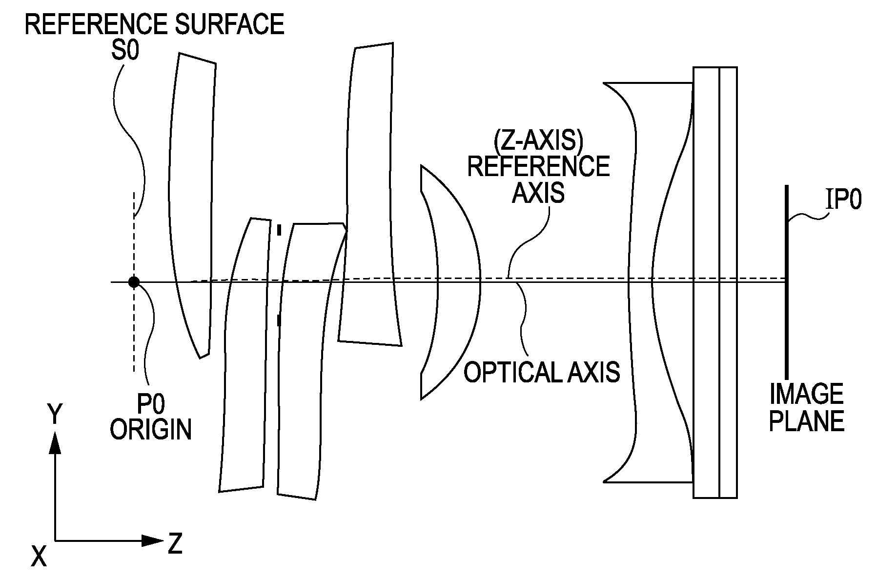
[0070]FIG. 1 is a lens sectional view according to a first exemplary embodiment of the present invention.

[0071] Referring to FIG. 1, reference characters T, M, and W denote a telephoto end (a zooming position with the least power of the entire system), a middle zooming position, and a wide angle end (a zooming position with the most power of the entire system), respectively.

[0072]FIG. 5 is a lens sectional view for illustrating each element at the middle zooming position according to the first exemplary embodiment.

[0073] The zoom optical system according to the first exemplary embodiment is an imaging lens system for use in an image-pickup apparatus, and in the lens sectional view, the left is the object side and the right is the image side.

[0074] The zoom optical system according to the first exemplary embodiment can also be used for a projector, and in this case, the left is a screen and the right is a surface to be projected.

[0075] Referring to FIGS. 1 and 5, in optical grou...

second exemplary embodiment

[0149]FIG. 23 is a lens sectional view according to a second exemplary embodiment of the present invention. The specification is the same as that of the first exemplary embodiment. However, F-numbers at the telephoto end and at the middle zooming position are 8.5 and 6.4, respectively. The optical system includes seven optical devices in total. The optical devices E1a, E2a, E3a, E4a, E5a, and E6a sequentially arranged from the object side are rotationally asymmetric and are off-centered in the Y axis direction, and their eccentricity is changed continuously. The positive / negative sign condition of the eccentricity is reverse to each other and the absolute value is the same. The optical devices E3a, E4a, and E7a are rotationally symmetric spheres; however, if aberration asymmetric about the optical axis remains, they can also be rotationally asymmetric for eliminating the aberration.

[0150] The optical devices E1a and E2a constitute the first optical group G1a. Similarly, the optical...

third exemplary embodiment

[0162]FIG. 29 is an explanatory drawing of a digital still camera using the zoom optical system according to the first exemplary embodiment as an image-pickup optical system. Referring to FIG. 29, reference numeral 20 denotes a camera body; numeral 21 an image-pickup optical system configured by the zoom optical system described with reference to FIG. 1; numeral 22 a solid-state image-pickup device (photoelectric transducer), such as a CCD sensor and a CMOS sensor, housed in the camera body for receiving object images formed by the image-pickup optical system; numeral 23 a memory for storing the information corresponding to the object images photo-electrically converted by the solid-state image-pickup device 22; and numeral 24 a finder which includes a liquid crystal display panel for observing object images formed on the solid-state image-pickup device 22.

[0163] In such a manner, by applying the zoom optical system according to at least one exemplary embodiment to an image-pickup ...


PUM


Abstract

At least one exemplary embodiment is directed to a zoom optical system which includes a plurality of optical groups with variable optical power arranged along an optical axis; and at least one optical group arranged along the optical axis, and where the system is zoomed by changing the power of at least one of the plurality of the optical groups with variable optical power, where the plurality of the optical groups with variable optical power each includes a rotationally asymmetric surface and each has a plurality of optical devices, which change the power within the respective optical groups by moving the respective optical devices in a direction different from the optical axis, and the system at a telephoto end satisfies the condition: |φdt|≦|φst|, where |φdt| is the absolute value of the power total sum of a plurality of the optical groups with variable optical power, and |φst| is the absolute value of the power total sum of the at least one optical group.

Description

BACKGROUND OF THE INVENTION [0001] 1. Field of the Invention [0002] The present invention relates to a zoom optical system which can be used in various devices such as an image-pickup apparatus, a projector, an aligner, and a reader. [0003] 2. Description of the Related Art [0004] Recently, along with the wide spread of digital cameras and mobile phones equipped with cameras, a compact and high-resolution zoom optical system has been demanded. [0005] In a compact and high-resolution zoom optical system, the system is generally zoomed by moving a plurality of lens groups relative to a light-receiving plane (such as a CCD) in the optical axial direction. In a conventional zoom system in which lens groups are moved toward an object, the entire optical length (the distance between a first lens surface and an image plane) is increased, restricting the entire lens system from being miniaturized. [0006] Whereas, an optical system has been discussed using an optical device called an Alvarez...

Claims


Application Information

Patent Timeline
IPC IPC(8): H01S3/00
CPCG02B15/02
Inventor YOSHIDA, HIROFUMIHATAKEYAMA, KOSHI
Owner CANON KK
Features
  • R&D
  • Intellectual Property
  • Life Sciences
  • Materials
  • Tech Scout
  • Unparalleled Data Quality
  • Higher Quality Content
  • 60% Fewer Hallucinations
Learn More