Digital camera with projector and digital camera system

a digital camera and projector technology, applied in the direction of printers, instruments, camera focusing arrangement, etc., can solve the problem that the camera does not ensure the maximum operability

Inactive Publication Date: 2006-12-28
NIKON CORP
View PDF16 Cites 31 Cited by
  • Summary
  • Abstract
  • Description
  • Claims
  • Application Information

AI Technical Summary

Benefits of technology

[0018] A digital camera equipped with a projector according to the first aspect may further include a photographing control device that controls the photographing device upon receiving a switching operation signal indicating a changeover to the photographing operation mode from the mode switching ope

Problems solved by technology

However, after the composite camera disclosed in the publication is switched to the projection operation mode to engage the projector device in operation, further operat

Method used


Image

  • Digital camera with projector and digital camera system
  • Digital camera with projector and digital camera system
  • Digital camera with projector and digital camera system

Examples


first embodiment

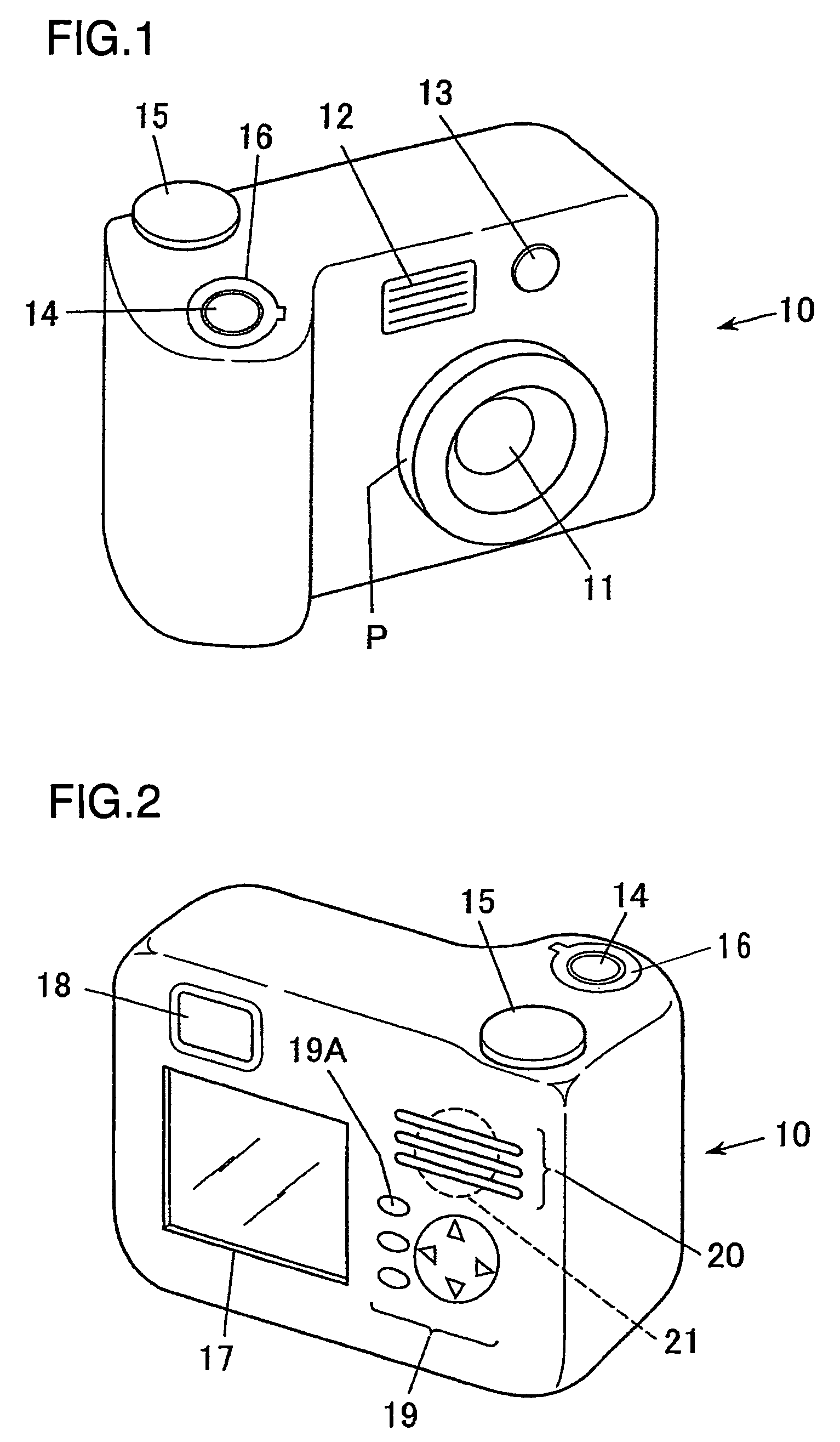
[0033]FIG. 1 is a perspective of a digital camera equipped with a projector, which is achieved in the first embodiment of the present invention, viewed from the front side of the digital camera (toward the subject). As shown in FIG. 1, a photographic lens 11, an illuminating light window 12 and a projection window 13 are disposed at the front of an digital camera 10 equipped with the projector. At the top surface (the surface of the casing turned to the upper side when the digital camera 10 is held sideways) of the digital camera 10 equipped with the projector, a shutter release button 14, a mode selector dial 15 and a main switch 16 are disposed.

[0034]FIG. 2 is a perspective of the digital camera equipped with the projector in FIG. 1, viewed from the rear side (toward the photographer). As shown in FIG. 2, a liquid crystal display unit 17, an electronic viewfinder 18, operation members 19 and speaker holes 20 are disposed at the rear surface of the digital camera 10 equipped with ...

second embodiment

[0082] The present invention may also be adopted in a system in which a rechargeable battery is used as a power source in a digital camera and a projector device is built into a digital camera auxiliary device that supplies the electrical current to the digital camera to charge the rechargeable battery. The digital camera auxiliary device is constituted as a cradle through which the charging current (power) may be supplied to the digital camera and which may project a reproduced image. Under normal circumstances, a photographing operation is not performed while the digital camera is mounted at the cradle.

[0083]FIG. 7 is a block diagram of a digital camera 10 constituting the digital camera system mounted at a cradle 20.

[0084] (Cradle)

[0085] The cradle 20 in FIG. 7 includes a projector unit 120, a CPU 151, a memory 152, an operation member 153, a video interface (VIDEO I / F) 155, a LAN interface (LAN I / F) 156, a USB interface (USB I / F) 157, an external power source circuit 158, a c...

third embodiment

[0112] The present invention may be adopted in a digital camera system that includes a digital camera equipped with a projector and a digital camera auxiliary device which is not equipped with a built-in projector device. FIG. 8 is a block diagram of such a digital camera system with a digital camera 10B equipped with a projector set on a cradle 20A. The same reference numerals are assigned to members in FIG. 8 identical to those in FIG. 7 in reference to which the second embodiment has been explained and their explanation is omitted. The digital camera 10B adopts an external structure similar to that of the digital camera 10 in FIGS. 1 and 2 and includes a cradle interface 110 that can be exposed to the outside as necessary.

[0113] A CPU 101B of the digital camera 10B makes a decision as to whether or not the digital camera 10B is currently set on the cradle 20A. The presence / absence of the digital camera 10B on the cradle may be judged based upon the signal value detected at a spe...


PUM


Abstract

A digital camera equipped with a projector, includes a photographing device; a projector device that projects an optical image; a mode switching operation member that outputs a switching operation signal indicating a changeover to one of a photographing operation mode in which image data photographed by the photographing device are saved as a photographic image file in a recording medium and a projection operation mode in which a reproduced image is projected by the projector device; a top surface operation member disposed at an upper surface of a casing; and a projection control device that controls the projector device based upon an operation signal provided by the top surface operation member upon receiving a switching operation signal indicating a changeover to the projection operation mode from the mode switching operation member.

Description

INCORPORATION BY REFERENCE [0001] The disclosures of the following priority applications are herein incorporated by reference: Japanese Patent Application No. 2005-031943 filed Feb. 8, 2005 Japanese Patent Application No. 2005-257694 filed Sep. 6, 2005 BACKGROUND OF THE INVENTION [0002] 1. Field of the Invention [0003] The present invention relates to a digital camera equipped with a projector that projects an optical image, and a digital camera system. [0004] 2. Description of Related Art [0005] Japanese Laid Open Patent Publication No. H8-146512 discloses a composite camera equipped with a projector function. As a projection mode switch or a video play button is operated, the composite camera shifts into a mode in which the projector is engaged in operation. [0006] However, after the composite camera disclosed in the publication is switched to the projection operation mode to engage the projector device in operation, further operations such as a selection of an image to be proje...

Claims


Application Information

Patent Timeline
IPC IPC(8): G03B19/00
CPCG03B17/54H04N9/3176H04N9/3141H04N5/225H04N23/00
Inventor NOZAKI, HIROTAKEFUJINAWA, NOBUHIROOHMURA, AKIRA
Owner NIKON CORP
Why Eureka
Try Eureka