Nut insert

Inactive Publication Date: 2006-12-28
MCGEE THOMAS +1
View PDF37 Cites 49 Cited by
  • Summary
  • Abstract
  • Description
  • Claims
  • Application Information

AI Technical Summary

Benefits of technology

[0009] Typically, a portion of the tool body, such as a threaded stud, provides the insert attachment means. The insert attachment means engages the sleeve member of the insert, such as by making up the threaded stud into internal threads within the sleeve of the insert. The insert is then placed within the aperture until the flange of the insert abuts the first side of the work piece, and the face of the nose piece abuts the flange on the other side. Upon activation, the reciprocation means connected to the insert attachment means causes the insert attachment means to be withdrawn into the tool body. At the same time, the nose piece of the installation tool, which abuts the

Problems solved by technology

However, installing non-round openings in the workpiece and manufacturing inserts having other than a roun

Method used


Image

  • Nut insert
  • Nut insert
  • Nut insert

Examples


Example

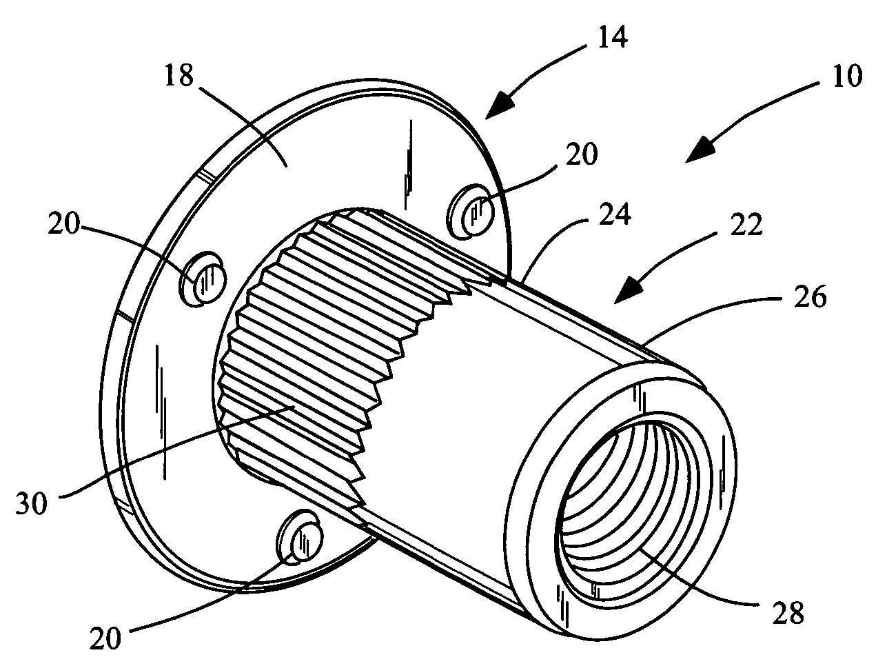
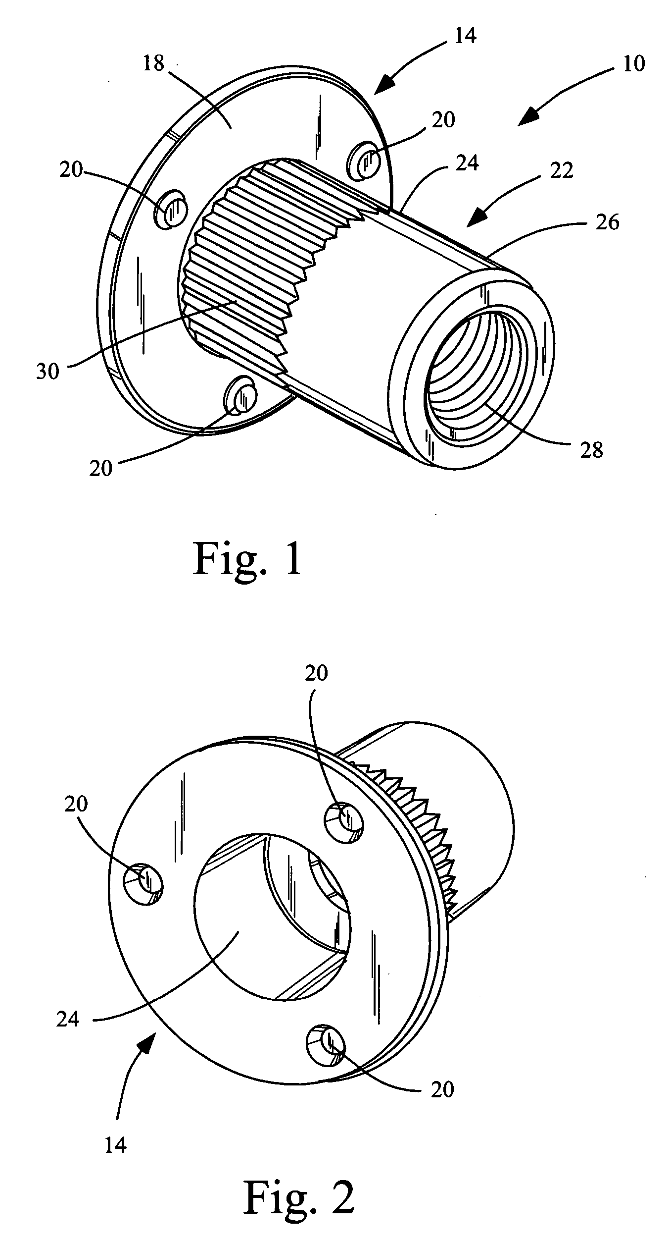
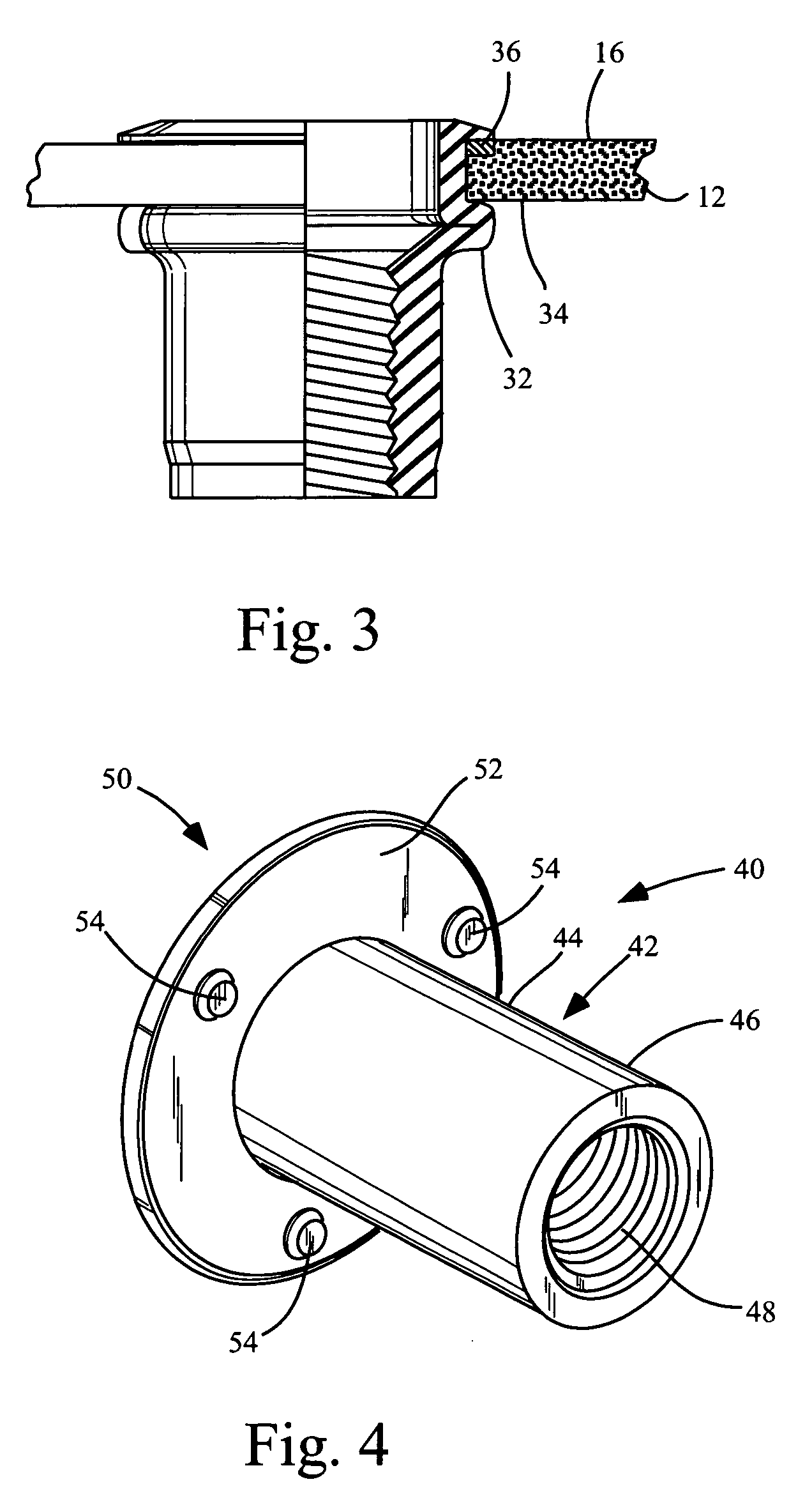
[0019] Referring now specifically to the drawings, FIG. 1 shows a perspective view of a first embodiment 10 of the disclosed nut insert as it appears before installing it within a workpiece 12 (shown in FIG. 3) prior to installation. Prior to installation of the nut insert the workpiece 12 will have been drilled, bored, or punched to create an aperture for insertion of one end of the nut insert. The embodiment 10 of the threaded insert depicted in FIG. 1 comprises a first flange 14 which is retained on the first side 16 of the workpiece 12. The first flange 14 further comprises a contact surface 18 which abuts the first side 16 of the workpiece 12. The contact surface 18 comprises one or more fusible contact members which are adapted to fuse to the workpiece 12 upon activation of the installation system. As shown in FIGS. 1 and 2, the fusible contact members may comprise material displaced from first flange 14 by punching first flange thereby creating a dimple 20 in the first flange...


PUM


Abstract

A nut insert which is installed within an aperture in a workpiece, the nut insert of the type in which a portion of the insert plastically deforms on the one side of the workpiece upon application of a linear force provided by a tool, thereby preventing withdrawal of the insert from the aperture. The nut insert comprises a sleeve member and an integral flange, where the flange has a larger diameter than the aperture, and the flange further comprises a contact surface for abutting the workpiece. The insert comprises fusible contact members which are adapted to fuse to the workpiece upon activation of the installation system, which includes current generation means.

Description

RELATED APPLICATIONS [0001] Assignee hereto is also the assignee of currently pending application Ser. No. 10 / 698,975.BACKGROUND OF THE INVENTION [0002] The present invention relates to an apparatus for attaching threaded fasteners to a workpiece, the workpiece having a first side and a second side. Usually the first side is a visible side and the second side is a blind side, meaning there is no access to the second side. More particularly, this invention relates to a nut insert which is used with an installation system which expands the body of the insert—such that the insert cannot be withdrawn from an aperture within the workpiece—while, nearly simultaneous to the expanding of the body of the insert, the system fuses a portion of the insert to the work piece. Appropriate fusing processes may include resistance welding and capacitor discharge welding. [0003] It is known to use threaded rivet nuts, threaded inserts, and threadable inserts, as anchors for threaded fasteners in a num...

Claims


Application Information

Patent Timeline
IPC IPC(8): F16B37/06
CPCB25B27/0014F16B37/067F16B37/061F16B11/006
Inventor MCGEE, THOMASNERI, FRANK
Owner MCGEE THOMAS
Why Eureka
Try Eureka