
Fuel equalization system

a fuel equalization and fuel technology, applied in the direction of combustion types, combustion processes, burners, etc., can solve the problems of corresponding harmful buildup of co, inability of sensors of known systems to accurately control the desired air/fuel mixture, and inability to accurately control the flow or air inlet conditions of blocked air, so as to reduce the turbulence of blocked air flow, prevent leakage, and reduce the number of clips

Inactive Publication Date: 2006-12-28
WESTCAST
View PDF26 Cites 2 Cited by
  • Summary
  • Abstract
  • Description
  • Claims
  • Application Information

AI Technical Summary

Benefits of technology

[0010] It is another object of the present invention is to provide a fuel equalization system which is capable of maintaining a desired air / fuel ratio even during times of blocked air flow.
[0011] It is another object of the present invention is to provide a fuel equalization system which reduces the turbulence of a blocked air flow.
[0012] A further object of the invention is to position the air and fuel inlet orifices some distance from the blower inlet, thereby isolating the air and fuel inlet orifices from excessive turbulence caused by any blockages.
[0013] A further object of the invention is to decrease the number of clips that are engaged about the respective connected adjacent flange portions to prevent leakage.
[0014] A further object of the invention is to provide a fuel equalization system which substantially eliminates the creation of harmful gas build-up during times of partially or completely blocked air flows.
[0015] In accordance, therefore, with one embodiment, it is an object of the present invention to provide a fuel equalization system includes a filter box for accepting an air stream and a fuel stream, the air stream and the fuel stream mixing to form a mixed air / fuel stream. A blower is provided that has an inlet for accepting the mixed air / fuel stream from the filter box. An air deflection member is positioned in the path of the mixed air / fuel stream, between the filter box and the inlet, so as to reduce the turbulence of the mixed air / fuel stream.

Problems solved by technology

Any blockage of the incoming air or fuel streams, or of the flue leading to the burner, will cause a change in the air / fuel mixture being fed to the burner, with a corresponding potential for the harmful buildup of CO.
While these systems operate reasonably well during normal times, they suffer under blocked-flue or blocked-air inlet conditions due to the swirling air currents created by these adverse conditions.
Thus, during times of blockages, the sensors of known systems are incapable of accurately controlling the desired air / fuel mixture, due to the swirling and turbulent implied flows washing over the sensors.
Known systems are therefore unable to accurately control the air / fuel mixture during times when the air inlet, or flue, is partially or completely blocked.

Method used


Image

  • Fuel equalization system
  • Fuel equalization system
  • Fuel equalization system

Examples


Embodiment Construction

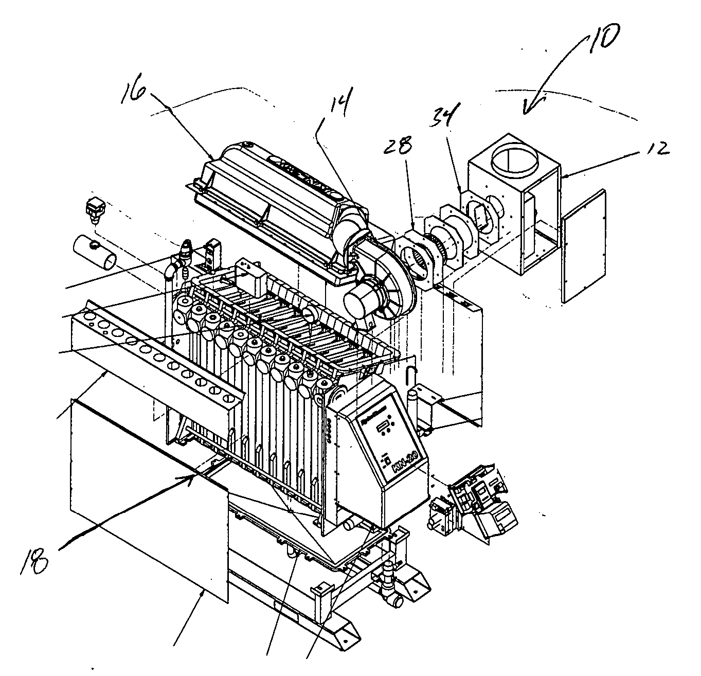
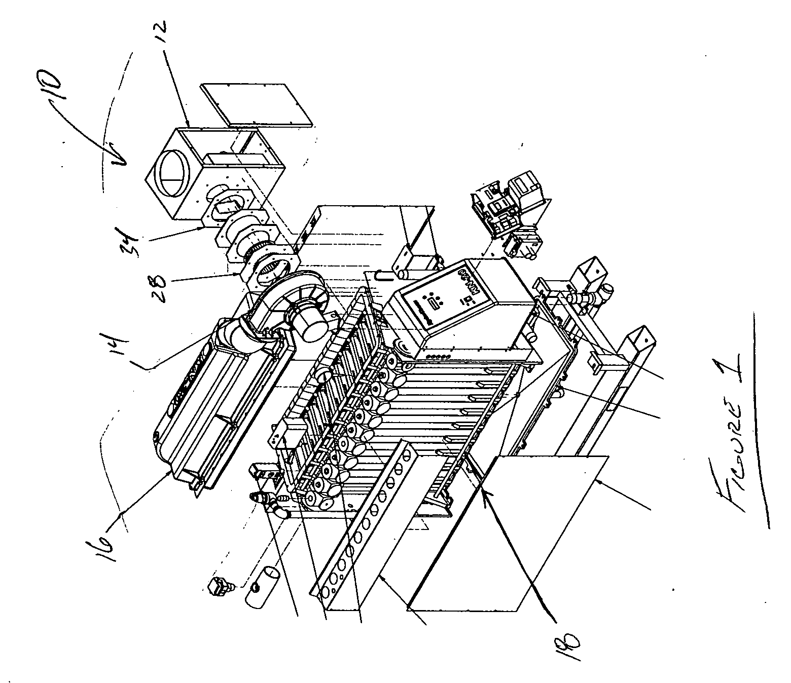
[0020]FIG. 1 illustrates an exploded view of a fuel equalization system 10, according to one embodiment of the present invention. As shown in FIG. 1, the fuel equalization system 10 includes a filter box 12 and a blower 14. An air / fuel stream is directed by the blower 14 to a burner assembly 16, which in turn is operatively connected to a boiler apparatus 18.

[0021] It will be readily appreciated that while the boiler apparatus 18 has been described in connection with FIG. 1, the present invention is not so limited in this regard as the blower 14 may be connected to any suitable apparatus without departing from the broader aspects of the present invention.

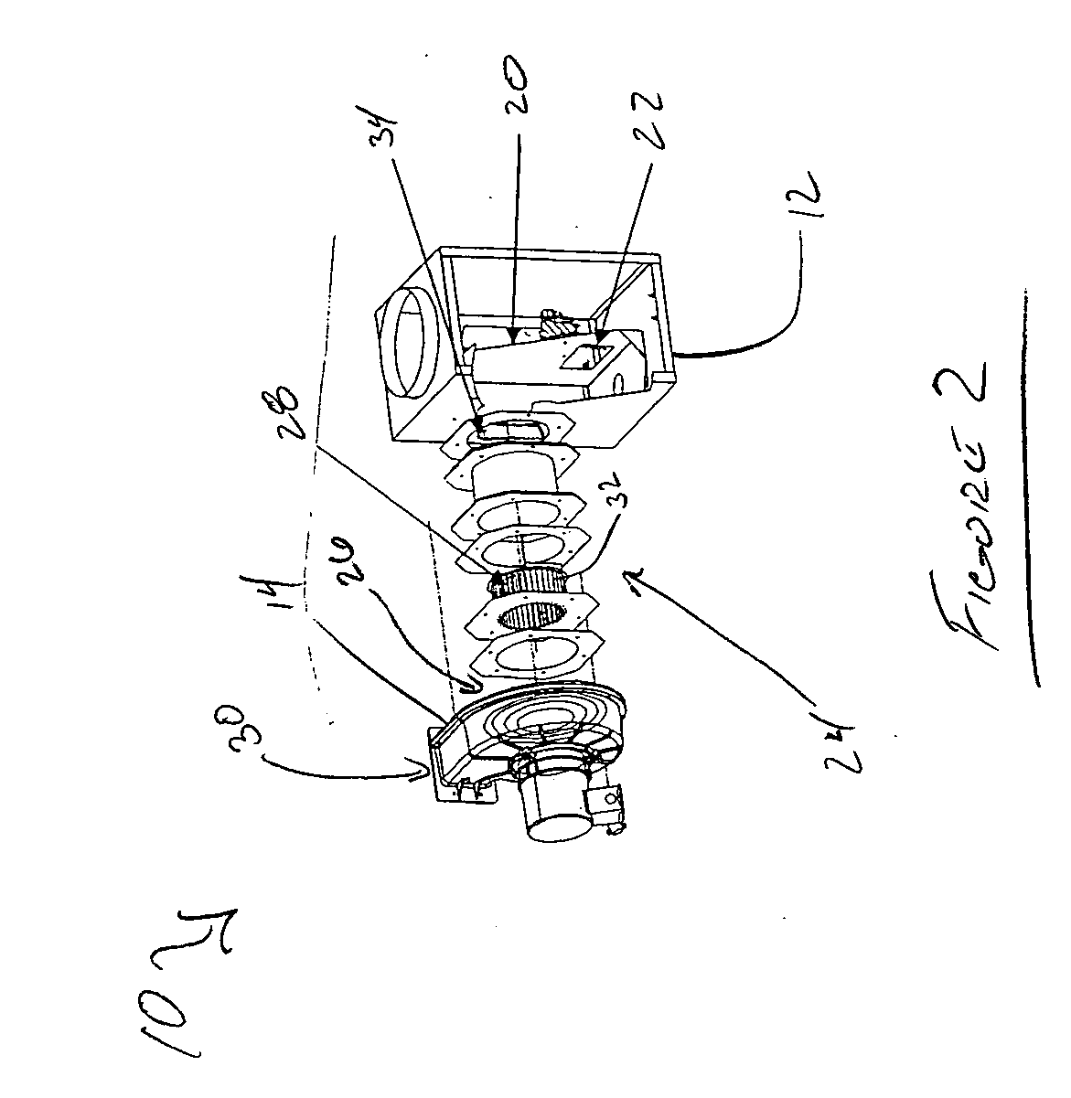
[0022]FIG. 2 illustrates the fuel equalization system in isolation. As shown in FIG. 2, the filter box 12 defines an inner box 20 having an air orifice and fuel entry 22. A duct section 24 is oriented between the filter box 12 and the blower 14. An air stream and a fuel stream are directed through the air orifice and fuel entry 22...


PUM


Abstract

A fuel equalization system includes a filter box for accepting an air stream and a fuel stream, the air stream and the fuel stream mixing to form a mixed air / fuel stream. A blower is provided that has an inlet for accepting the mixed air / fuel stream from the filter box. An air deflection member is positioned in the path of the mixed air / fuel stream, between the filter box and the inlet, so as to reduce the turbulence of the mixed air / fuel stream.

Description

CROSS REFERENCE TO RELATED APPLICATIONS [0001] This application claims the benefit of U.S. Provisional Application Ser. No. 60 / 680,805, filed on May 13, 2005, and herein incorporated by reference in its entirety.FIELD OF INVENTION [0002] The present invention relates, in general, to a fuel equalization system, and deals more particularly with a fuel equalization system that is capable of maintaining proper air / fuel mixtures even during times of decreased or blocked air flow. BACKGROUND OF THE INVENTION [0003] Burners are utilized in many integrated systems, such as in boilers, furnaces and water heater applications. These burners are typically fed an enriched air stream containing a predetermined concentration of fuel mixed therein. Of great importance, therefore, is the ability of the system to maintain a proper air / fuel mixture during operation of the system. [0004] Typically, a filter box includes one or more orifices to accept incoming air and fuel streams. A blower is operative...

Claims


Application Information

Patent Timeline
Patent Type & Authority Applications(United States)
IPC IPC(8): F24H7/00
CPCF23D14/36F23M9/02F23D14/68
Inventor COHEN, KENNETH W.
Owner WESTCAST
Learn More