
Apparatus and method for static resistance training

a training apparatus and static resistance technology, applied in the field of static resistance training equipment, can solve problems such as pressing against fully static devices and structures

Inactive Publication Date: 2006-12-28
RAST RODGER H
View PDF0 Cites 31 Cited by
  • Summary
  • Abstract
  • Description
  • Claims
  • Application Information

AI Technical Summary

Benefits of technology

[0009] The invention provides a safe training device for static resistance training with numerous advantages. It should be appreciated that in a traditional weight training system movement is achieved in response to overcoming the weight of the free weight or the weight setting of the weight stack. In the present invention the machine is set for a static force. The device can have a fixed input, wherein user pressure does not cause the input handle(s), feet plate, or whatever form of input device group is utilized, to move in response to the pressure application (for example movement less than 2″).
[0012] It should be noted that even though the body device group, or a portion thereof, is adapted to move over a distance (preferably a small distance, such as less than 6″ and more preferably less than 3″). One embodiment allows the body device group to move from a ready position to a use position whose extent strikes the end point (no further movement—or restricted as with biasing device) at which pressure input is registered in the selected range.
[0016] Controlled feedback pressure—system configured with adjustable biasing potential, wherein user can adjust the level of feedback received.
[0017] Vibratory Muscle Response Inducement (VMRI)—a small force displacement means at a frequency approximately equal to or greater than 1 Hz provides enhanced muscle training in response to automatic muscle force accommodation to train muscles faster.
[0019] Electronic selection of time and / or reps—system allows user to set the target time for holding the weight, a number of reps in which pressure is applied to the target weight, or both.
[0024] The invention can be incorporated within a separate machine of the Incorporated with these devices according to one embodiment a position is selected, such as by insertion of a weight select value, which provides the static setting. By way of example a static “weight” setting is beyond the other weights in the stack (i.e., after 250 pounds on a cable-lift-weight machine (i.e., Nautilus® Brand)). When positioned on this setting the user can apply high levels of static force which are registered by the system and annunciated to provide the static workout benefits.

Problems solved by technology

However, pressing against fully static devices and structures has a number of disadvantages.

Method used


Image

  • Apparatus and method for static resistance training
  • Apparatus and method for static resistance training
  • Apparatus and method for static resistance training

Examples


first embodiment

[0064] In the machine a body group device, lat pull, bench press, leg press or other form of apparatus adapted for receiving a force applied by the user, is configured with the action device. The action device is defined herein as being the movable part on a standard weight machine, which is configured for static or semi-static retention on this apparatus.

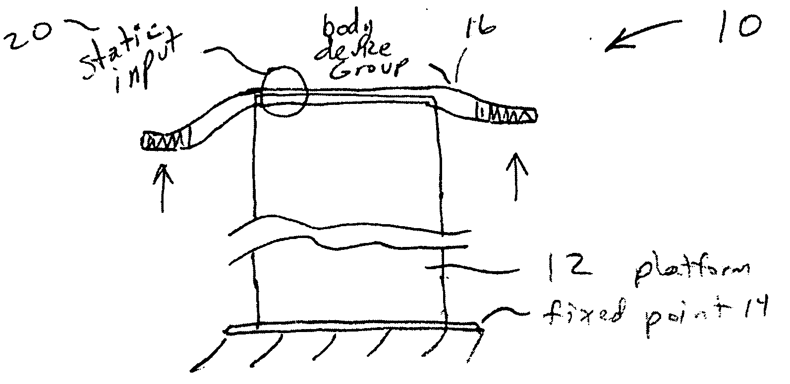
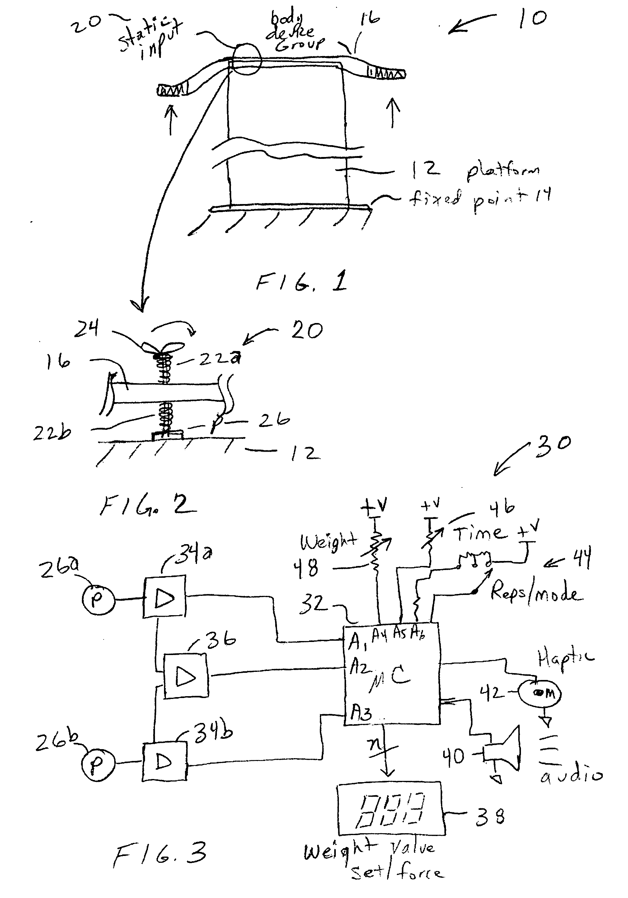
[0065]FIG. 1 is an example of the static training device 10, having a base 12 upon fixed platform 14. A body device group element 16 is shown with semi-static input element 20. In this mode semi-static input element 20 is adapted for providing a limited compliance adjustment to control the feel when pressure is applied to the body device group 16.

[0066]FIG. 2 illustrates an embodiment of adjustable feedback mechanism. In this simple illustration body device group 16 contains a bar which is shown mounted with compliant elements 22a, 22b upon retention member 24 coupled to sensor 26, which is adapted for sensing static force / pressur...

embodiment 50

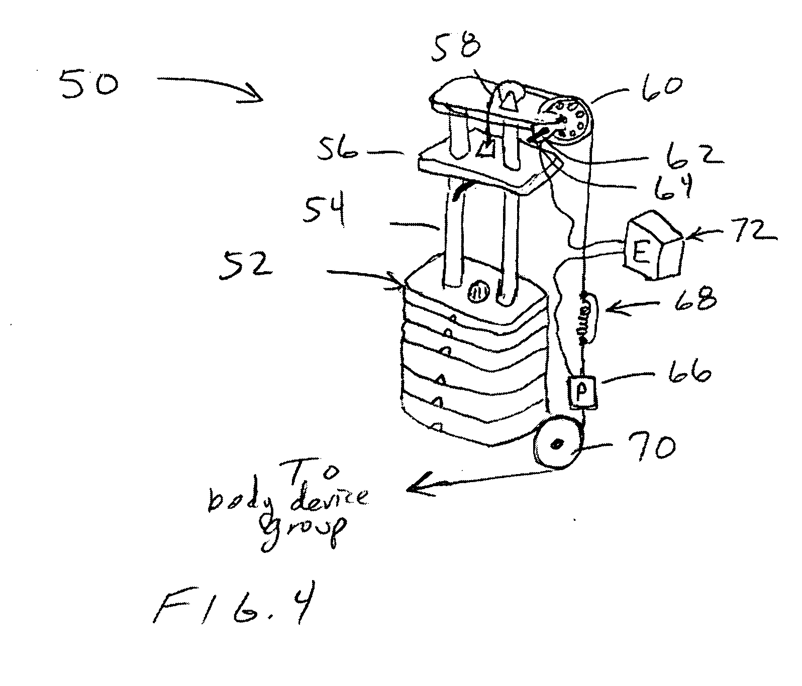
[0071] In FIG. 4 an embodiment 50 of a static force registration device is incorporated within a conventional non-static training devices, such as those incorporating movable weights. In this manner the devices can be used for both static training and dynamic training. It will be appreciated that the system can be preferably “locked” at a given position for static training wherein the user can practice static force application at any desired position along the normal travel path of the machine. For example locked so as to apply force near the arms fully-extended position, or any desired position along the range of conventional motion.

[0072] By way of example and not limitation, a weight stack is 52 shown adapted for being conventionally displaced along track 54. A first weight plate 56 is shown selected, such as via a weight selection pin, and moved to a desired position for static training. In this example the first plate is moved in response to a cable 58, such as through pulleys,...

embodiment 10

[0113]FIG. 5 illustrates an embodiment 10 of the electroactivated starter pistol having a housing 12 that is not readily confused with a weapon and yet it has a handle 14 with a trigger 16, such that pulling the trigger activates the starting sequence of the device. A base 18 is shown into which a pyro strip 20 can be inserted. A user interface 30 is shown with selectors for setting the mode of operation, timing cadence, level of randomness, and other aspects of operation. A small display 32 is shown (e.g., electronic ink, LED, LCD, etc.) for displaying any desired status information. Alternatively, or additionally, discrete status indicators are utilized such as LEDs for indicating state, mode, and so forth.

[0114]FIG. 6 depicts an example of the percussion device strip, for example pyrotechnic (pyro) strip 20, having a base material 21 which forms a printed circuit for electrically establishing connections with each pyro element 22, (i.e., plastic, paper, phenolic, fiberglass, or s...


PUM


Abstract

A system and method for performing static strength training. The system provides tactile feedback as well as directing the user in the proper application of sufficient and balanced force.

Description

CROSS-REFERENCE TO RELATED APPLICATIONS [0001] This application claims priority from provisional patent application Ser. No. 60 / 694,466 filed Jun. 27, 2005, incorporated herein in its entirety.STATEMENT OF FEDERALLY SPONSORED RESEARCH OR DEVELOPMENT [0002] Not Applicable REFERENCE TO A MICROFICHE APPENDIX [0003] Not Applicable BACKGROUND OF THE INVENTION [0004] 1. Field of the Invention [0005] This invention pertains generally to physical training devices and more particularly to a static resistance trainer apparatus. [0006] 2. Description of the Background Art [0007] It has been found that physical strength training can be sped up by the use of static resistance training. In this the user presses against a very high amount of weight to move it just the slightest amount and repeats the exercise. However, pressing against fully static devices and structures has a number of disadvantages. [0008] Therefore, a need exists for a static training device that provides feedback to the user w...

Claims


Application Information

Patent Timeline
IPC IPC(8): A63B71/00
CPCA63B21/0023A63B21/062A63B24/00F41C3/04A63B2071/0627A63B2220/51A63B2225/50A63B2071/0625A63B21/0628
Inventor RAST, RODGER H.
Owner RAST RODGER H
Learn More