Cuff and sleeve system for gastrointestinal bypass

a gastrointestinal bypass and sleeve technology, applied in the direction of surgical staples, blood vessels, surgical forceps, etc., can solve the problems of not being able to effectively reduce the volume of the stomach nor being configured

Inactive Publication Date: 2006-12-28
VALENTX
View PDF99 Cites 99 Cited by
  • Summary
  • Abstract
  • Description
  • Claims
  • Application Information

AI Technical Summary

Benefits of technology

The present invention provides an attachment system for attaching a device to the gastrointestinal tract. The system includes a gastrointestinal attachment cuff and an attachment structure for transmural attachment of the cuff to the mucosal side. The attachment structure has a connecting element for extending through the wall and a transverse retention surface for positioning in contact with the serosal tissue. The cuff may be a unitary annular component or assembly, or may comprise two or three or more components spaced circumferentially apart about a longitudinal axis. The technical effect of this invention is to provide a reliable and secure attachment system for attaching devices to the gastrointestinal tract.

Problems solved by technology

This patent discusses different ways to address the problem of excess body fat and how to improve their treatment. However, one technical problem still remaining is the lack of a suitable device that can be easily deployed perorally and attached securely in the intestine to promote weight loss without affecting nutrient uptake.

Method used


Image

  • Cuff and sleeve system for gastrointestinal bypass
  • Cuff and sleeve system for gastrointestinal bypass
  • Cuff and sleeve system for gastrointestinal bypass

Examples


Embodiment Construction

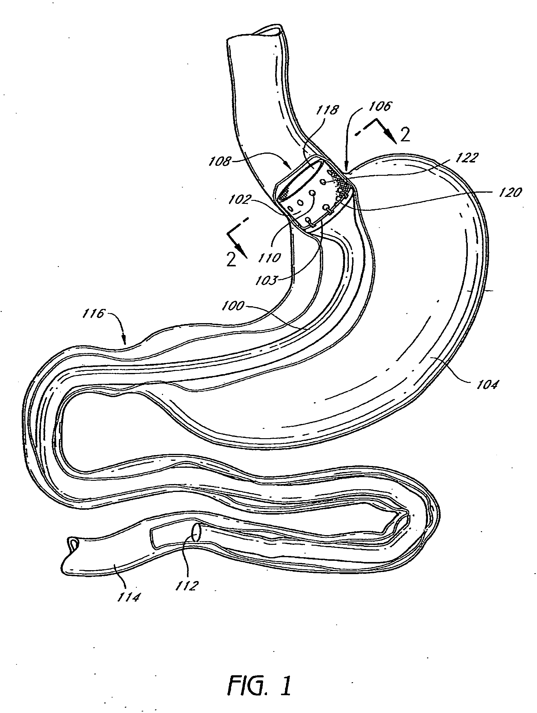
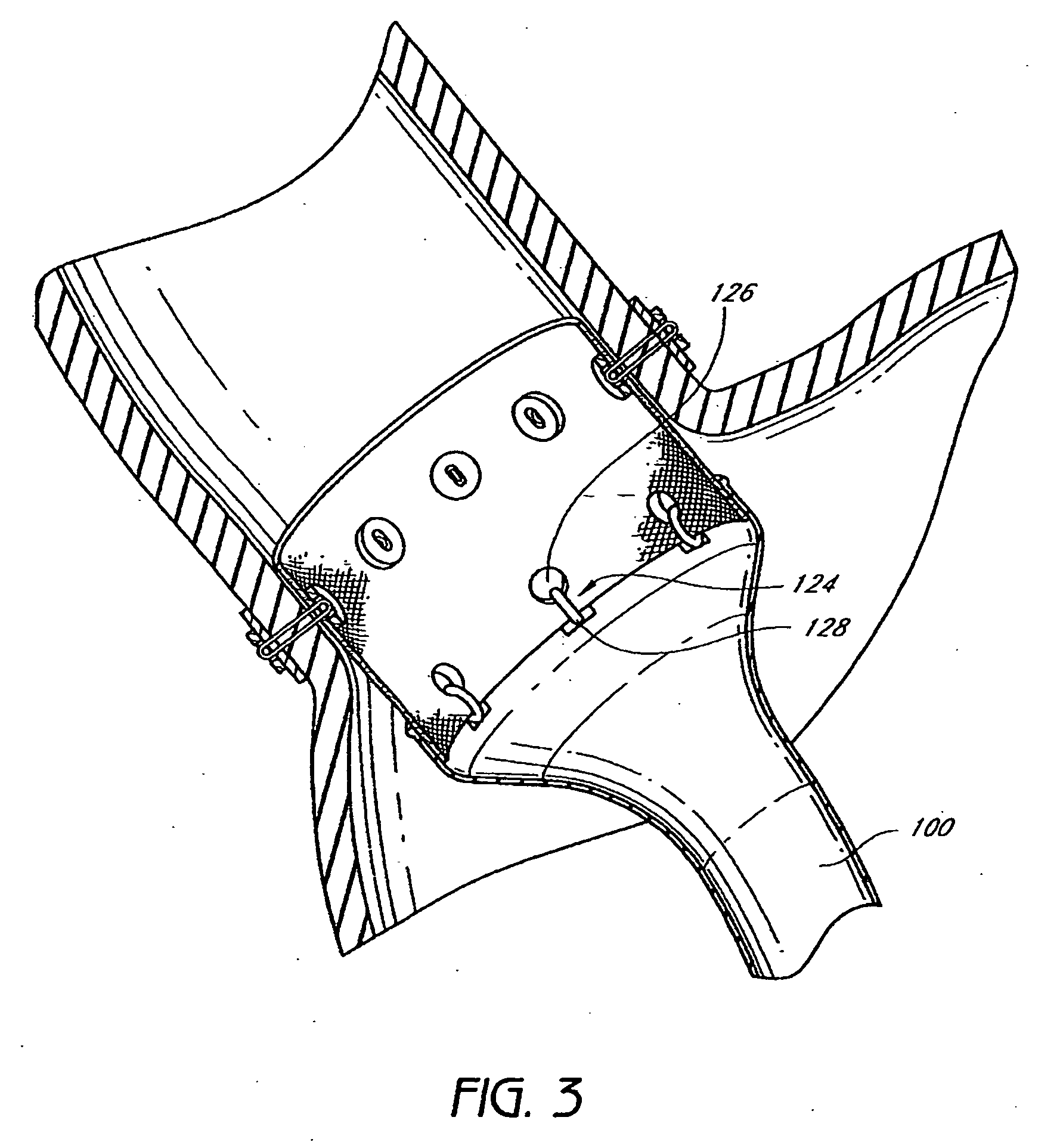
[0043] The present invention provides devices and methods for attaching an implant within the gastrointestinal system. Although described primarily in the context of supporting an endolumenal bypass sleeve, the attachment technology of the present invention can be utilized to support any of a variety of devices which may be desirably positioned within the stomach or elsewhere in the gastrointestinal system. For example, the attachment cuff and / or serosal anchors disclosed herein may be utilized to support any of a variety of valves or constricted openings designed to treat gastroesophageal reflux disease (GERD), by augmenting natural function of the lower esophageal sphincter or replacing that function. Any of a variety of obesity devices may also be attached to the attachment cuff and / or using the serosal anchors disclosed herein, such as electrical stimulation and / or pacing devices, or volume occupying devices which hang from or are otherwise attached to the vicinity of the lower ...


PUM


Abstract

The present invention provides devices and methods for attachment of an endolumenal gastrointestinal device, such as an artificial stoma device, a gastrointestinal bypass sleeve or other therapeutic or diagnostic device, within a patient's digestive tract. In one application of the invention, an endolumenal bypass sleeve is removeably attached in the vicinity of the gastroesophageal junction to treat obesity and/or its comorbidities, such as diabetes. The bypass sleeve may be at least partially deployed by eversion.

Description


Claims


Application Information

Patent Timeline
Owner VALENTX
Why Eureka
Try Eureka