Method and device for detecting contaminant on condenser lens in laser processing machine

a laser processing machine and contaminant technology, applied in the direction of optical elements, manufacturing tools, instruments, etc., can solve the problems of complicated processing head configuration and lower processing efficiency, and achieve the effect of reducing the focal length

Inactive Publication Date: 2007-01-04
YAMAZAKI MAZAK KK
View PDF10 Cites 24 Cited by
  • Summary
  • Abstract
  • Description
  • Claims
  • Application Information

AI Technical Summary

Benefits of technology

[0013] According to the present invention, as a contaminated condenser lens in a laser processing machine thermally expands and its focal length is reduced, the contaminant on the condenser lens can be detected by simple means.

Problems solved by technology

Any contaminants such as extraneous materials adhering to the optical system or the condenser lens lower the efficiency of the processing.
However, the means makes the configuration of the processing head complicated and requires another processing of the imaged data.

Method used


Image

  • Method and device for detecting contaminant on condenser lens in laser processing machine
  • Method and device for detecting contaminant on condenser lens in laser processing machine
  • Method and device for detecting contaminant on condenser lens in laser processing machine

Examples


Embodiment Construction

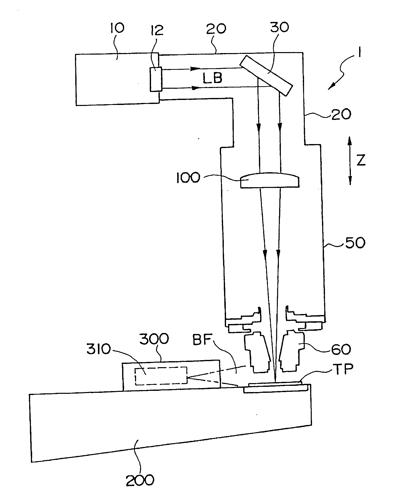
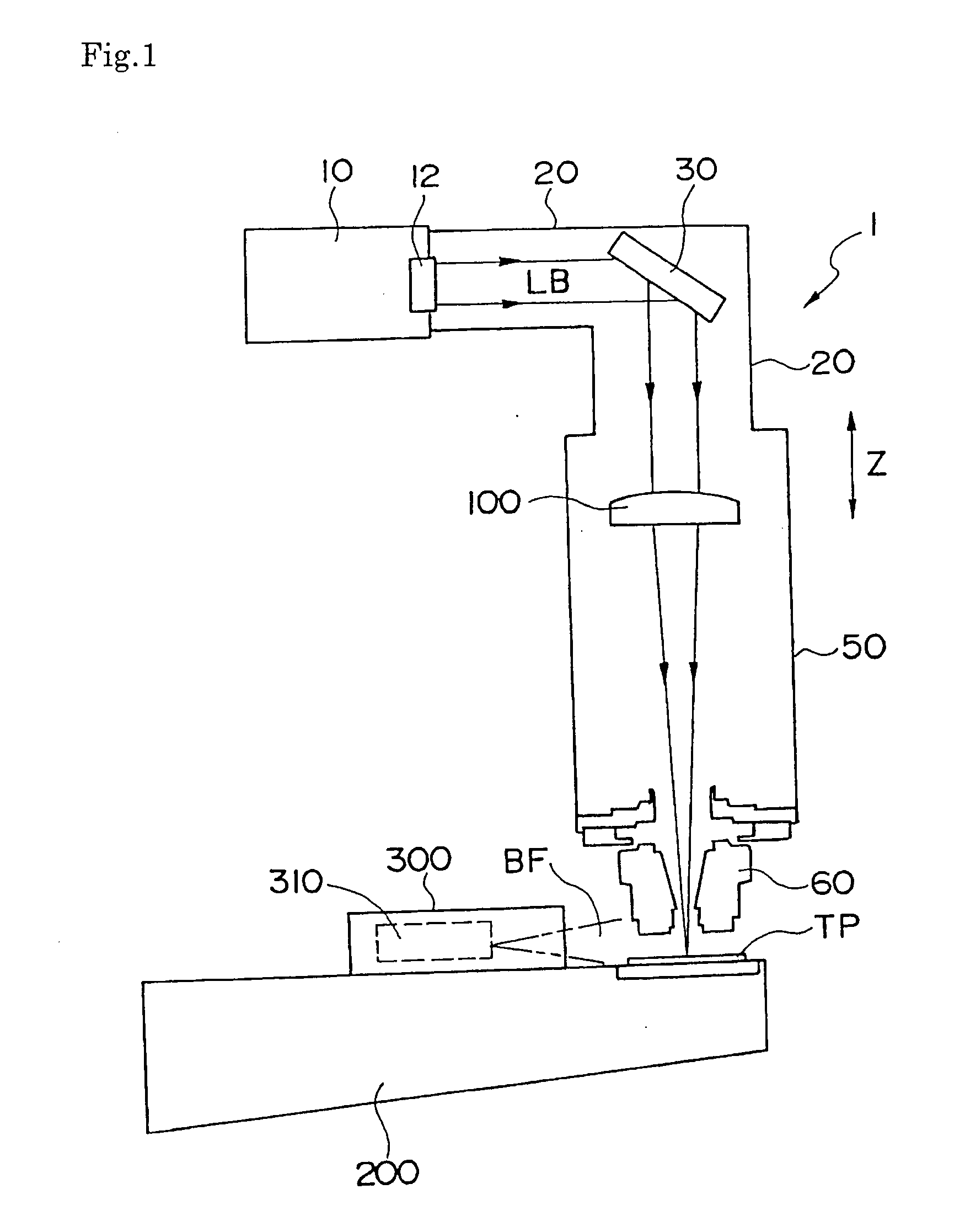
[0017]FIG. 1 is a view to generally illustrate a device for detecting a contaminant on a condenser lens in a laser processing machine according to the present invention.

[0018] A device for detecting a contaminant on a condenser lens which is generally denoted by reference numeral 1 comprises a light receiving device 300 mounted on a part of a base 200 in a laser processing machine. The light receiving device 300 has a light sensor 310 to detect an intense light which is called a blue flame BF, the intense light being generated when the focal point of the condensed laser beam falls on a surface of a test piece TP.

[0019] A laser resonator 10 in the laser processing machine outputs a laser beam LB through an output lens 12 to a light path 20. A turning mirror 30 or the like is arranged in the light path 20 to introduce the laser beam LB into a processing head 50.

[0020] The processing head 50 is controlled to move relative to the fixed light path 20 in the Z axis direction which is v...


PUM

PropertyMeasurementUnit
focal lengthaaaaaaaaaa
radius of curvature R1aaaaaaaaaa
light transmittanceaaaaaaaaaa

Abstract

A technology is provided in which a contaminant on a condenser lens in a laser processing machine is detected by detecting a change in focal lengths of the lens. A laser beam LB emitted from a laser resonator 10 is condensed by a condenser lens 100 in a processing head 50 to be irradiated from a nozzle 60 toward a test piece TP. A control device of the laser processing machine controls the moving of the processing head 50 in the Z axis direction and records the Z coordinate of the head. When a focal point falls on a surface of the test piece TP, a blue flame BF is generated. A light receiving device 300 receives the blue flame and sends a signal to the control device. In a contaminated condenser lens 100, a heat is accumlated, which expands the lens and reduces the focal length of the lens. A contaminant on the condenser lens is detected by using this change.

Description

[0001] The present application is based on Japanese patent application No. 2004-359402 filed on Dec. 13, 2004, the entire contents of which are hereby incorporated by reference. BACKGROUND OF THE INVENTION [0002] 1. Field of the Invention [0003] The present invention relates to an automatic device for detecting a contaminant on a condenser lens equipped in a torch of a laser processing machine. [0004] 2. Description of the Related Art [0005] In a laser processing machine, a laser beam is emitted from a laser emitter to be supplied via an optical system having a turning mirror to a processing torch which includes a condenser lens where the laser beam is condensed on a position close to a surface of a work to perform a processing. [0006] Any contaminants such as extraneous materials adhering to the optical system or the condenser lens lower the efficiency of the processing. [0007] Japanese Patent Laid-Open Publication No. 9-271968 (Patent Document 1) discloses a technology for detecti...

Claims


Application Information

Patent Timeline
Patent Type & Authority Applications(United States)
IPC IPC(8): B23K26/02B23K26/00
CPCB23K26/04B23K26/426G02B27/0006G01N2021/157G01N21/15B23K26/705
Inventor YAMAZAKI, TSUNEHIKOMIYAKAWA, NAOOMI
Owner YAMAZAKI MAZAK KK
Why Eureka
Try Eureka