Device for generating a pulsed magnetic field

a pulsed magnetic field and device technology, applied in the direction of magnetic circuit rotating parts, magnetic circuit shape/form/construction, instruments, etc., can solve the problems of large eddy current in all metal components, unsatisfactory pressure build-up in the cryostat, and significant increase in the cold mass

Inactive Publication Date: 2007-01-04
SIEMENS HEALTHCARE GMBH
View PDF17 Cites 24 Cited by
  • Summary
  • Abstract
  • Description
  • Claims
  • Application Information

AI Technical Summary

Benefits of technology

[0014] It is therefore an aspect of the invention to provide a device for generating a pulsed magnetic field, in which the problems resulting from the eddy currents generated by the pulse operation are minimized.

Problems solved by technology

If the magnet becomes quenched, i.e. the magnet changes from the superconducting state to the normal conducting state because of a jump in temperature, then an undesired pressure build-up takes place in the cryostat as the helium evaporates.
A disadvantage, however, is that depending on the distance between the cold head and the object to be cooled, the large cross sections necessary for thermal coupling lead to a significant increase in the cold mass.
Particularly for applications in magnetic resonance machines, this constitutes a problem since spatially extended magnet systems necessarily require longer cooling times.
A problem—independent of the aforementioned field of use—when using such AC or pulse coils, however, is that in any event the pulse operation causes large eddy currents in all the metal components of the cooling system, which may be made of copper.
These cause ohmic losses which stress the cooling system.
The eddy currents, which generate their own magnetic field, also cause deviations from the desired magnetic field profile of the coil, which impairs the imaging quality in magnetic resonance equipment.

Method used


Image

  • Device for generating a pulsed magnetic field
  • Device for generating a pulsed magnetic field
  • Device for generating a pulsed magnetic field

Examples


Embodiment Construction

[0032] Reference will now be made in detail to the preferred embodiments of the present invention, examples of which are illustrated in the accompanying drawings, wherein like reference numerals refer to like elements throughout.

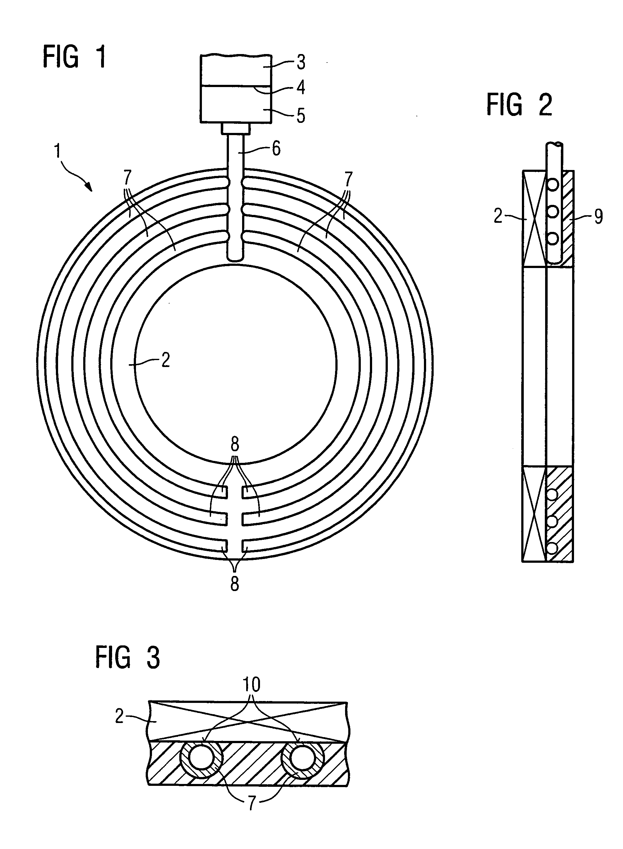
[0033]FIG. 1, like all the other views, only shows details essential for the invention. A device 1 is shown, having a winding 2 of superconducting material which forms the magnet. The winding 2 is designed as a disk winding or disk coil and it may be formed, for example, by a strip 4 mm wide and 0.25 mm thick which has been wound to form the disk and which contains superconductor material, preferably high-Tc superconductor materials such as (Bi,Pb)2Sr2Ca2Cu3O. The winding 2 can of course be connected as usual via contact means (not shown in detail) to a corresponding pulse or alternating-current supply, etc., in order to generate a pulsed magnetic field.

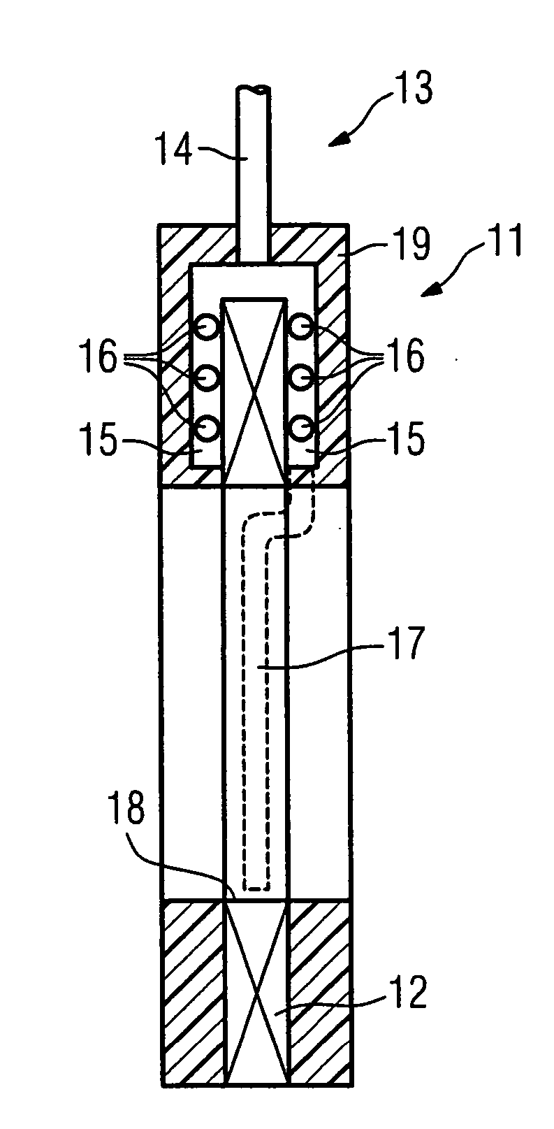
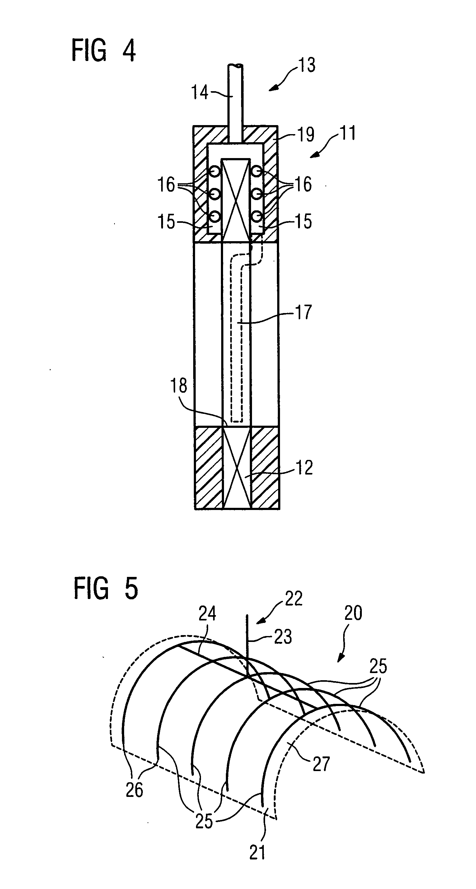
[0034] A refrigerating unit (not shown in detail), with at least one cold head 3 located at its cold end...


PUM


Abstract

A pulsed magnetic field is generated by a device having a magnet to be operated in pulse operation which contains at least one superconductive refrigerant-free winding that is disk-shaped or saddle-shaped. Also included is a refrigerating unit which has at least one cold head. A line system, having a refrigerant circulating in it according to a thermosiphon effect, thermally couples the winding to the cold head. The line system has a plurality of separate pipes lying next to one another. The pipes, open onto a common refrigerant distributor and closed at the other end, are thermally coupled to the surface of the disk-shaped or saddle-shaped winding.

Description

CROSS REFERENCE TO RELATED APPLICATIONS [0001] This application is based on and hereby claims priority to German Application No. 10 2005 028 414.0 filed on Jun. 20, 2005, the contents of which are hereby incorporated by reference. BACKGROUND OF THE INVENTION [0002] 1. Field of the Invention [0003] The invention relates to a device for generating a pulsed magnetic field, with a magnet to be operated in pulse operation which contains at least one superconductive refrigerant-free winding. [0004] 2. Description of the Related Art [0005] Besides the metal superconductor materials known for a long time, for example NbTi or Nb3Sn, which have very low transition temperatures Tc and are therefore referred to as low-Tc superconductor materials or LTS materials, metal oxide superconductor materials with transition temperatures Tc above 77 K are also known. The latter materials are also referred to as high-Tc superconductor materials or HTS materials. [0006] Attempts are also being made to cons...

Claims


Application Information

Patent Timeline
Patent Type & Authority Applications(United States)
IPC IPC(8): H02K41/00H02K9/00H02K3/00H02K1/22
CPCG01R33/3804H01F6/04G01R33/3815
Inventor KRUIP, MARCEL JAN MARIEOOMEN, MARIJN PIETERHASSELT, PETER VAN
Owner SIEMENS HEALTHCARE GMBH
Why Eureka
Try Eureka