Vibration-damping receiving element

a technology of receiving element and vibration, which is applied in the direction of machine supports, dynamo-electric machines, domestic objects, etc., can solve the problems of not being able to implement many design attempts, the elastic element cannot expand beyond the boundaries of its original size, etc., and achieves good damping, good damping, and good damping

Inactive Publication Date: 2007-01-04
NITZSCHE HARTMUT
View PDF3 Cites 24 Cited by
  • Summary
  • Abstract
  • Description
  • Claims
  • Application Information

AI Technical Summary

Benefits of technology

[0003] By contrast, the elastic vibration-damping mounting according to the present invention offers the advantage that, on the elastic element, a free bridge is formed by the positioning of the support surfaces on components of the assembly and the mounting fixed to the frame in a laterally offset position. In the related art, the elastic element is only pressed together by clamping, and is not able to expand beyond the boundaries of its original size. In the present invention, however, a free bridge is developed, which permits a shearing motion of the elastic element, transversely to the direction of the vibration. By a shearing motion we mean, in this instance, the superposition of a torsional motion and a bending motion, and not a shearing movement having the effect of shearing off material. This shearing motion results in the extension of the elastic element, also transversely to the direction of the vibration. Depending on the extent of the deflection, an extreme extension is possible, for example, while forming an S-shaped form of the free bridge, since there is enough space available. This space is present based on the “freedom” of the free bridge, that is, since it is not clamped in between components. When unloaded, the elastic element once more takes up its initial size, based on the restoring force. The magnitude of the restoring force comes about due to the elastic properties of the material of the elastic elements. Upon being unloaded, the elastic element contracts in the opposite direction to that in which it extended before. There is created a relatively large freedom of motion for the elastic element, which leads to corresponding movements of same. Compared to the related art, by the creation of a new possibility of motion in a direction transverse to the vibrational direction, namely, permitting the shearing movement of the elastic element, a very good damping is achieved. From this, there arises the advantage that the changes in length and volume changes that are achieved, which the elastic element goes through during the squeezing together and the extension in the present invention, is of a different kind than that in the related art. In the related art, only a pressing together of the elastic element is permitted, having short changes in length, conditioned by the distance apart of the support forces of the components. Consequently, the present invention achieves a softer, more effective damping. Independently of the embodiment of the damping mechanism and the clamping device per se, the structural embodiment of the mounting that is fixed to the frame, especially the space required in the motor vehicle for accommodating the assembly in the mounting that is fixed to the frame, is similar to the type of construction described in the related art. This is relevant, since the mounting that is fixed to the frame, for example, a blower flange in a motor vehicle, is not able to be made larger at will. Because of the boundary conditions on the space available in a limited way for the mounting that is fixed to the frame, up until the present, not many design attempts were able to be implemented for the improved damping of the accommodation of an assembly in a mounting fixed in the frame.

Problems solved by technology

In the related art, the elastic element is only pressed together by clamping, and is not able to expand beyond the boundaries of its original size.
Because of the boundary conditions on the space available in a limited way for the mounting that is fixed to the frame, up until the present, not many design attempts were able to be implemented for the improved damping of the accommodation of an assembly in a mounting fixed in the frame.

Method used


Image

  • Vibration-damping receiving element
  • Vibration-damping receiving element
  • Vibration-damping receiving element

Examples


Embodiment Construction

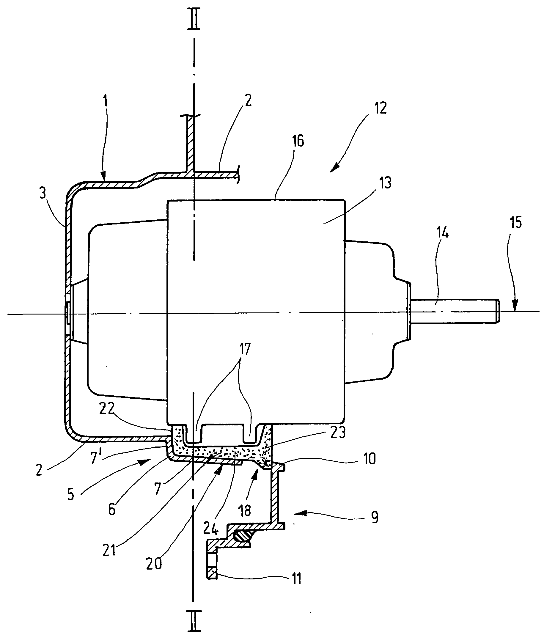
[0024]FIG. 1 shows a mounting 1 of a blower flange fixed to the frame. The blower flange is, for example, a blower flange of an air conditioning or heating system in a motor vehicle.

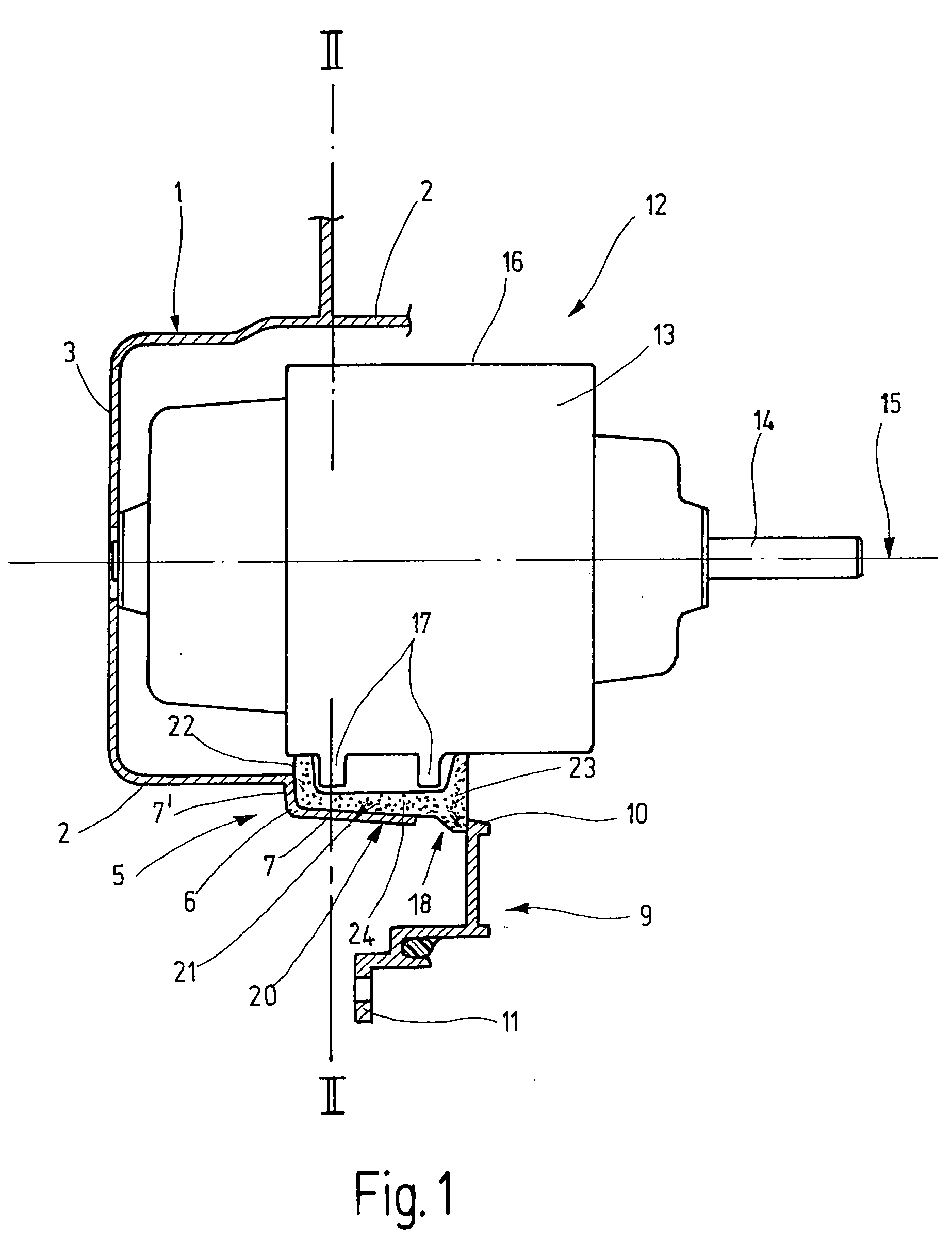
[0025] Mounting 1 fixed on the frame has a predominantly pot-shaped form, having a cylindrical sidewall 2 and a bottom 3. At side wall 2, a protuberance 5 is shown, which forms a pocket 6 that is described in more detail in FIG. 2. It has a pocket bottom 7 and a pocket end face 7′, as well as pocket side walls 8 and 8′ shown in FIG. 2. In this figure, only pocket bottom 7 and pocket end face 7′ are shown. In addition, mounting 1 that is fixed to the frame has a projection 9, whose constructive interplay with the pot-shaped part of mounting 1, that is fixed to the frame, is not shown in this figure. This projection 9 has a free end 10 facing side wall 2, and a free end 11 facing away from side wall 2.

[0026] In mounting 1 that is fixed to the frame, there is situated an assembly 19, in this case an elect...


PUM


Abstract

The present invention relates to a device for the elastic, vibration-damping accommodation of an assembly with respect to a mounting fixed to a frame, having at least one elastic element that is situated between the assembly and the mounting that is fixed to the frame, the assembly having at least one first support surface, and the mounting having at least one second support surface, and the two support surfaces face each other and run transversely, especially at right angles, to the vibrational plane of the vibration and, as seen in the direction of vibration, the elastic element lies in an overlapping position to the support surfaces. It is provided that the two support surfaces have a lateral clearance from each other, and that the first elastic element bridges the clearance in the form of a first free bridge.

Description

FIELD OF THE INVENTION [0001] The present invention relates to an elastic, vibration-damping mounting of an assembly with respect to a holding device that is fixed in the frame, having at least one elastic element. BACKGROUND INFORMATION [0002] Elastic, vibration-damping mountings according to the definition of the species are known. Such a vibration-damping mounting is especially intended to dampen torsional vibrations. To do this, at least one elastic element is situated between a component of the assembly and a component of the mounting that is fixed to the frame. The elastic element is made of a yielding material, preferably an elastomer. Because of forces such as the ones that occur in vibrations, the elastic element is deformed mechanically, for instance, pressed together, and therewith takes up the energy of the vibration. Because of its restoring behavior, the elastic element takes up once more its original shape and size. This process will repeat, so that a part of the ener...

Claims


Application Information

Patent Timeline
Patent Type & Authority Applications(United States)
IPC IPC(8): H02K5/24F16M9/00F16F15/04
CPCH02K5/24F16F15/04
Inventor NITZSCHE, HARTMUT
Owner NITZSCHE HARTMUT
Why Eureka
Try Eureka