Liquid crystal display device

Active Publication Date: 2007-01-04
PANASONIC LIQUID CRYSTAL DISPLAY CO LTD +1
View PDF5 Cites 43 Cited by
  • Summary
  • Abstract
  • Description
  • Claims
  • Application Information

AI Technical Summary

Benefits of technology

[0035] To be brief, the advantage provided by the representative ones of the inventions disclosed in this specification is that the l

Problems solved by technology

However, since it is necessary to visually check the engaging portions 1a formed in the sidewall of the mold 11 and the through holes 1b in the frame 16, for the purpose of seeing wh

Method used


Image

  • Liquid crystal display device
  • Liquid crystal display device
  • Liquid crystal display device

Examples


embodiment 1

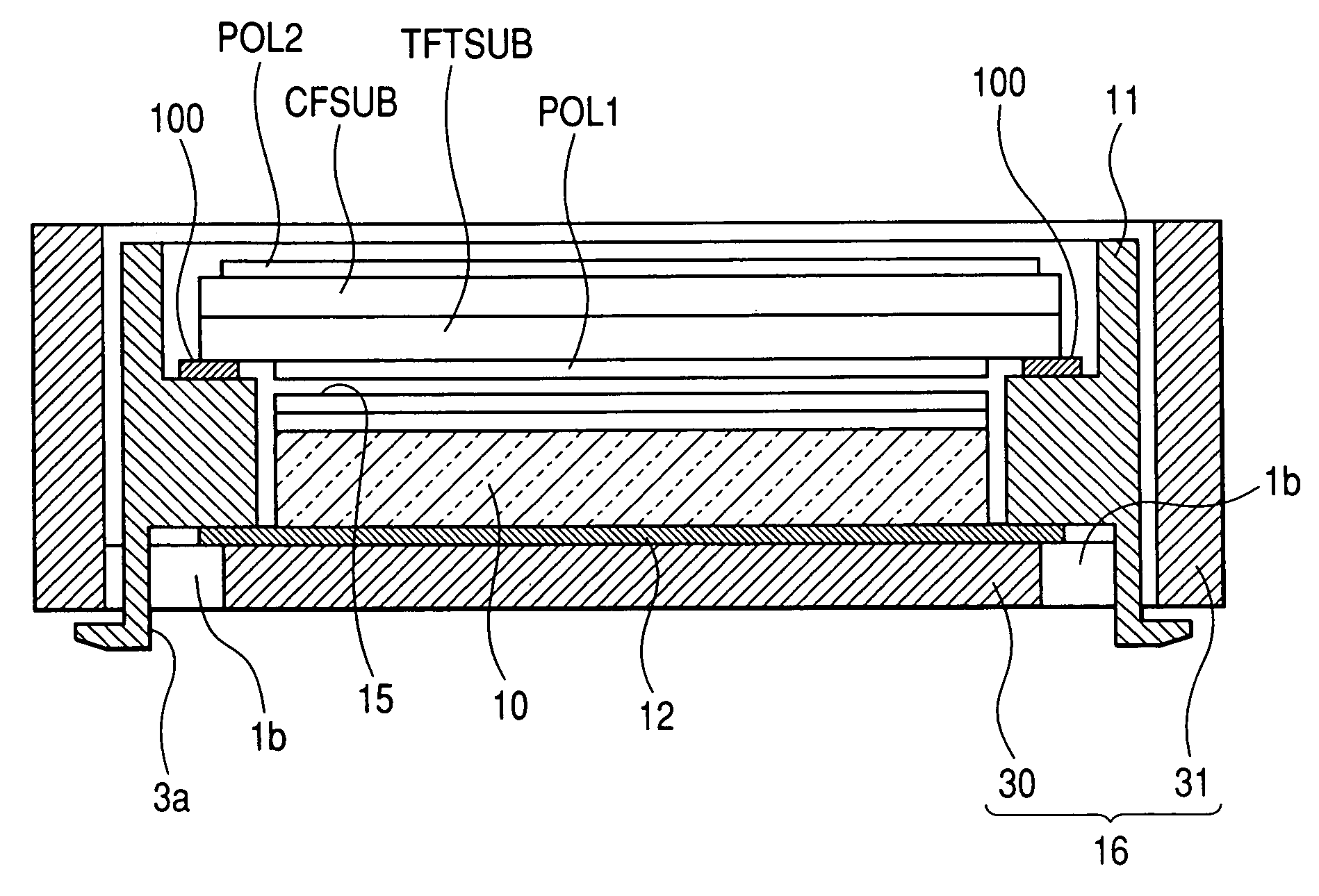
[0089] As in the case of the liquid crystal display panel LCD illustrated in FIGS. 16A and 16B, a liquid crystal display panel LCD in accordance with Embodiment 1 is fabricated by attaching together a glass substrate TFTSUB provided with thin film transistors, drain lines, gate lines and others (not shown) and a glass substrate CFSUB provided with a counter electrode, color filters and others (not shown) with a sealing agent (not shown) interposed therebetween, then filling a liquid crystal material (not shown) into a space between the two glass substrates TFTSUB, CFSUB, and sealing off the space, and then attaching polarizing sheets POL1 and PLO2 on the outer surfaces of the two glass substrates TFTSUB and CFSUB, respectively.

[0090] Since the present invention does not relates to an internal structure of the liquid crystal display panel LCD, the explanation of the details of the internal structure is omitted. The present invention is applicable to liquid crystal display panels LCD...

embodiment 2

[0100] Prior to explaining Embodiment 2, a problem will be explained which may arise in Embodiment 1. FIGS. 4A and 4B are rear views of the above-explained liquid crystal display module of Embodiment 1, FIG. 4A is a rear plan view of the liquid crystal display module, and FIG. 4B is an enlarged view of a circled portion, designated C, of FIG. 4A. FIG. 4C is an illustration for explaining the problem which may arise in the configuration of Embodiment 1 shown in FIG. 3C.

[0101] In the configuration of Embodiment 1, as shown in FIG. 3C, a rectangular light reflective sheet 12 is disposed on the bottom portion 30 of the frame 16. In this case, a step 33 is formed on a surface of the mold 11 on its light-reflective-sheet-12 side for positioning the light reflective sheet 12. As shown in FIGS. 3C and 4B, the edge portion (the edge portion of the long side) of the light reflective sheet 12 and the step 33 is disposed over the through hole 1b made in the bottom portion 30 of the frame 16. I...

embodiment 3

[0107] As in the case of the frame 16 shown in FIG. 18D and utilized for the prior art explained in connection with FIGS. 17A to 19C, the frame 16 utilized for this Embodiment 3 is provided with through holes 1b extending from the bottom portion 30 of the frame 16 into the sidewall 31 of the frame 16. However, in Embodiment 3, the size of the through holes 1b in the frame 16 are reduced such that the edge portions (the edge portions of the long sides) of the light reflective sheet 12 or the steps 33 of the mold 11 are not visible through the through holes 1b made in the bottom portion 30 of the frame 16.

[0108]FIG. 8A is an illustration for explaining the frame 16 in accordance with Embodiment 3, and shows a through hole 1b made in the bottom portion 30 of the frame 16. For comparison purposes, FIG. 8B is an illustration for showing the through hole 1b made in the prior art frame 16 explained in connection with FIGS. 17A to 19C. Here FIGS. 8A and 8B are enlarged views of the through...


PUM


Abstract

A liquid crystal display device includes a liquid crystal display panel having liquid crystal material sandwiched between a pair of substrates, optical components disposed behind the liquid crystal display panel, a frame-like mold which houses the liquid crystal display panel and the optical components, and a frame which houses the frame-like mold. The frame includes a bottom portion and a sidewall, and the bottom portion is provided with plural engaging through holes which are formed along the sidewall not to extend into the sidewall. The frame-like mold is provided with plural engaging protrusions which are disposed correspondingly to the engaging holes and protrude downward beyond a lower surface of the frame-like mold. The frame-like mold and the frame are fixed together by inserting each of the engaging protrusions into a corresponding one of the engaging through holes.

Description

CLAIM OF PRIORITY [0001] The present application claims priority from Japanese application serial no. 2005-189234, filed on Jun. 29, 2005, the content of which is hereby incorporated by reference into this application. BACKGROUND OF THE INVENTION [0002] The present invention relates to a liquid crystal display device, and in particular to a technology useful for application to a backlight of a liquid crystal display device. [0003] Widely used as display sections of portable equipment such as mobile phones are TFT (Thin Film Transistor) type liquid crystal display modules each provided with a small-sized color liquid crystal panel having subpixels in the order of 240×320×3 in number. [0004]FIG. 16A is a schematic exploded perspective view illustrating a rough configuration of a conventional liquid crystal display module. As shown in FIG. 16A, in the conventional liquid crystal display module, arranged in the order shown in FIG. 16A within a metal frame 16, for example, a die cast fra...

Claims


Application Information

Patent Timeline
IPC IPC(8): G02F1/1333
CPCG02F1/133308G02F2201/465G02F2001/133314G02F1/133314G02F1/1333
Inventor SHIRAI, KOUICHI
Owner PANASONIC LIQUID CRYSTAL DISPLAY CO LTD
Why Eureka
Try Eureka