
Method and system for processing scanned patches for use in imaging device calibration

a technology for imaging devices and patches, applied in colour separation/tonal correction, digital marking record carriers, instruments, etc., can solve the problems of less-than-efficient calibration tasks and printers, and achieve the effects of reducing noise, reducing noise, and reducing nois

Active Publication Date: 2007-01-04
XEROX CORP
View PDF68 Cites 31 Cited by
  • Summary
  • Abstract
  • Description
  • Claims
  • Application Information

AI Technical Summary

Benefits of technology

[0030] Scanner characterization and scanner-based printer calibration usually involve scanning patches and then averaging the pixels in the central portion of the patch. Averaging reduces noise and emulates the effect of the spectrophotometer aperture; using only the central portion avoids any stray colorant from adjacent patches, as well as providing some protection against misregistrati

Problems solved by technology

A problem is that, due to manufacturing variations, environmental conditions and usage histories, different imaging devices can output different intensities of color based on identical image data.
Traditionally, calibrating printers (e.g. any apparatus, such as a digital copier, bookmaking machine, facsimile machine, multi-function machine, etc. which performs a print outputting function for any purpose) has proven to be a less-than-efficient task, particularly if large amounts of data (e.g. test patches) are used.

Method used


Image

  • Method and system for processing scanned patches for use in imaging device calibration
  • Method and system for processing scanned patches for use in imaging device calibration
  • Method and system for processing scanned patches for use in imaging device calibration

Examples


Embodiment Construction

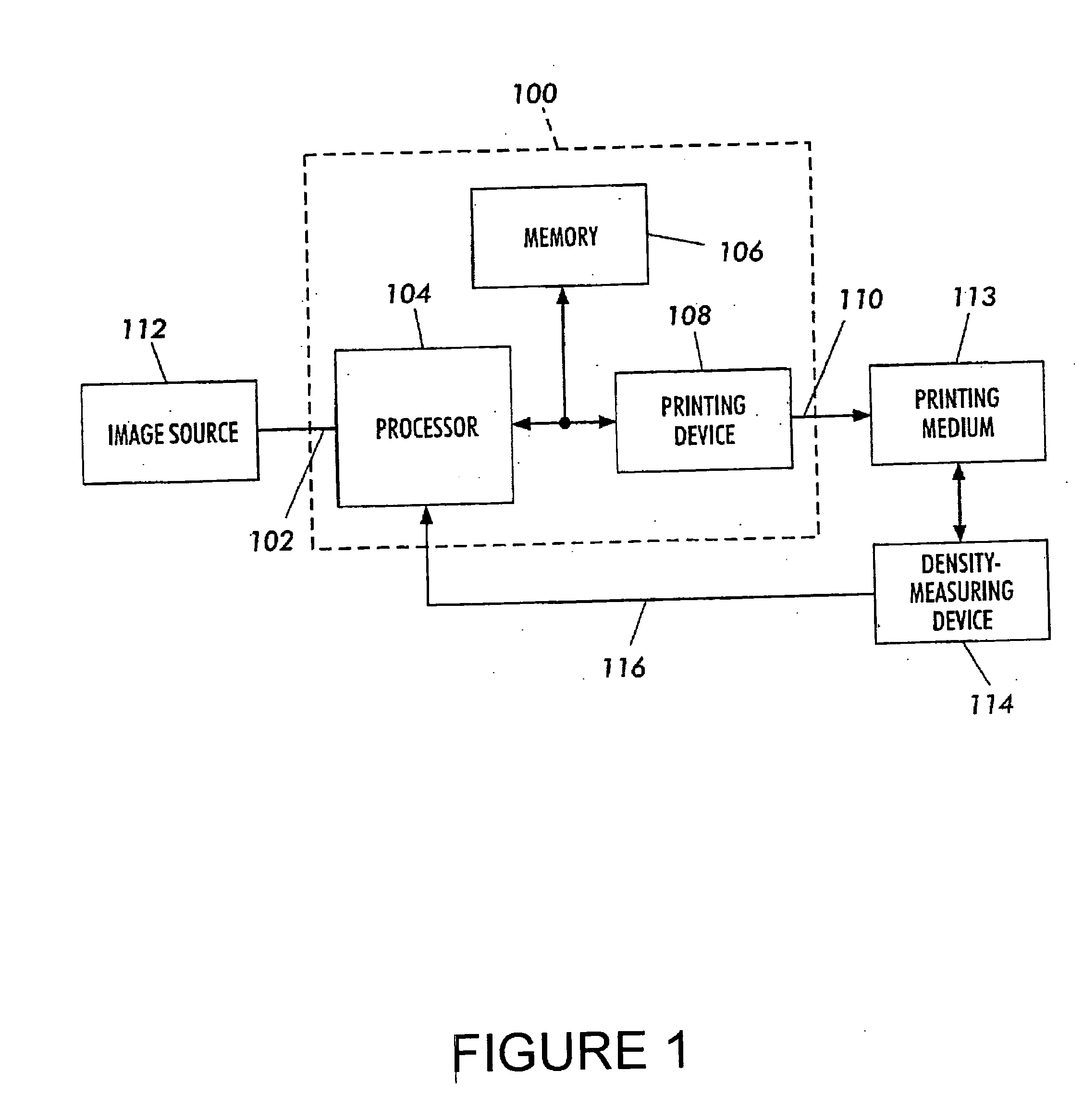
[0064]FIG. 1 shows a system that prints test patches, measures color output values of the test patches, and calibrates the color output characteristics of the system based upon the measured color output values. The system includes an arrangement 100 according to the presently described embodiments, an image source 112, a print medium 113, and a color-measuring device 114.

[0065] The arrangement 100 includes an input 102, a processor 104, a memory 106, a printing device 108, and an output 110. In general, the arrangement receives at the input 102 an image and generates at the output 110 printed pages of recording media from which the image may be physically reconstructed.

[0066] The image source 112 can be any suitable device that generates image data corresponding to a two-dimensional image. The image source 112 is further configured to provide image data corresponding to an array of rows and columns of test patches that are used to calibrate the arrangement 100, as will be discusse...


PUM


Abstract

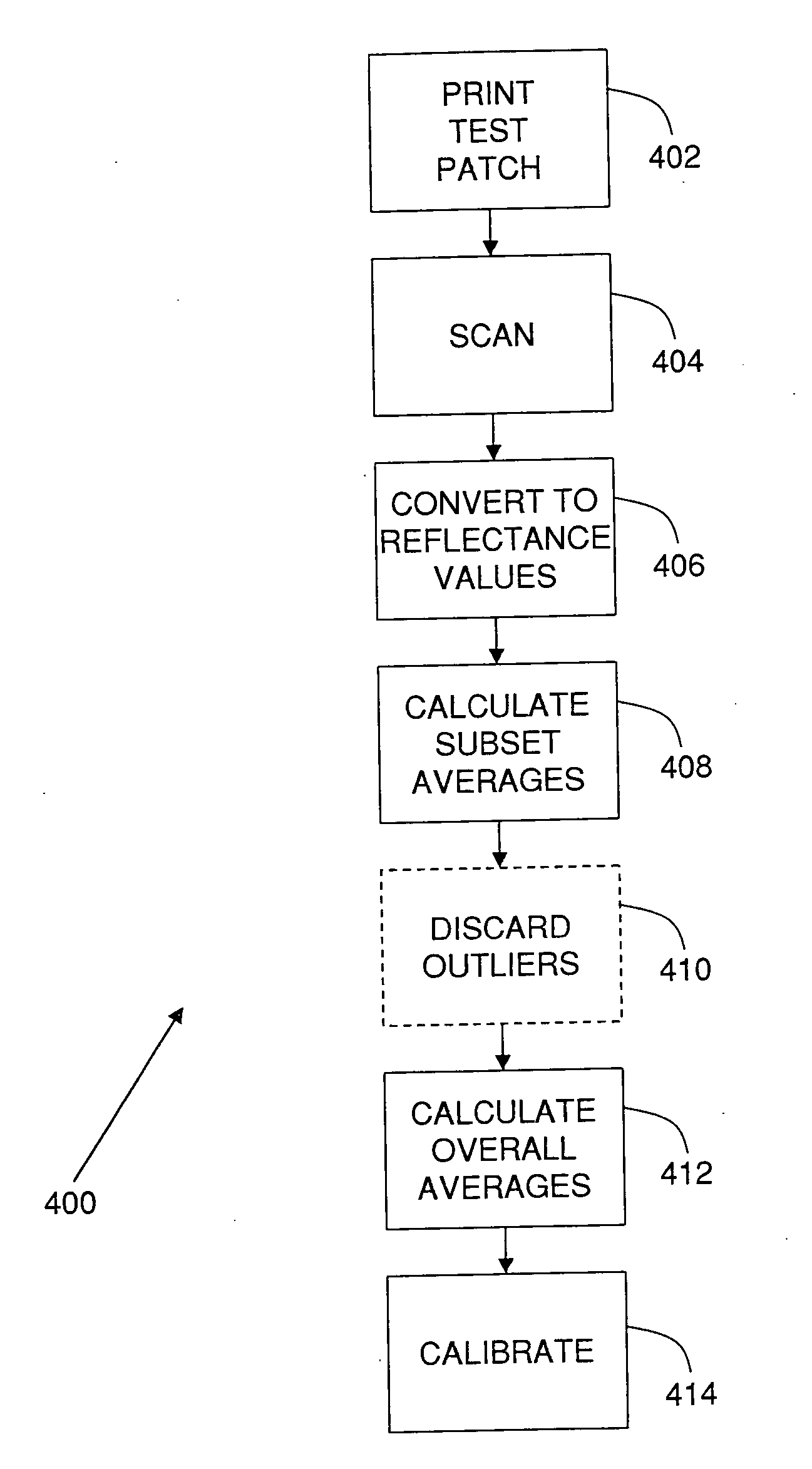
The presently described embodiments provide for halftone-aligned averaging and noise reduction in a calibration method and associated system. Halftone-aligned averaging is implemented, in one form, as a method of averaging in which the window over which an average is computed is a multiple of the halftone period. Noise reduction, in one illustrative embodiment, comprises discarding windows having an average outside of the range from the 5th to the 95th percentiles of all windows for a patch.

Description

CROSS REFERENCE TO RELATED PATENTS AND APPLICATIONS [0001] This application is related to U.S. application Ser. No. 10 / 372,558, filed Feb. 23, 2003 and having a Publication No. U.S. 2004 / 0165199 A1. [0002] The following applications, the disclosures of each being totally incorporated herein by reference are mentioned: [0003] U.S. Provisional Application Ser. No. 60 / 631,651 (Attorney Docket No. 20031830-US-PSP), filed Nov. 30, 2004, entitled “TIGHTLY INTEGRATED PARALLEL PRINTING ARCHITECTURE MAKING USE OF COMBINED COLOR AND MONOCHROME ENGINES,” by David G. Anderson, et al.; [0004] U.S. Provisional Patent Application Ser. No. 60 / 631,918 (Attorney Docket No. 20031867-US-PSP), filed Nov. 30, 2004, entitled “PRINTING SYSTEM WITH MULTIPLE OPERATIONS FOR FINAL APPEARANCE AND PERMANENCE,” by David G. Anderson et al.; [0005] U.S. Provisional Patent Application Ser. No. 60 / 631,921 (Attorney Docket No. 20031867Q-US-PSP), filed Nov. 30, 2004, entitled “PRINTING SYSTEM WITH MULTIPLE OPERATIONS F...

Claims


Application Information

Patent Timeline
IPC IPC(8): H04N1/46
CPCH04N1/4078
Inventor KLASSEN, R. VICTOR
Owner XEROX CORP
Learn More