Image decoding device and image decoding method

a decoding device and image technology, applied in the field of image decoding apparatus and image decoding method, can solve the problems of inability to cope with a coding amount (bit rate) lower than that in the mpeg1, coding method at a higher compression rate, and inability to perform correct decoding, etc., to achieve the effect of shortening the tim

Inactive Publication Date: 2007-01-04
SONY CORP
View PDF8 Cites 67 Cited by
  • Summary
  • Abstract
  • Description
  • Claims
  • Application Information

AI Technical Summary

Benefits of technology

[0110] As a result, with this image decoding method, not all picture data but part or all of it is decoded as simple playback frames in the fast playback mode, resulting in being capable of performing decoding in shorter time than a normal speed playback mode.

Problems solved by technology

The MPEG2 mainly executes high picture quality coding for broadcasting, but cannot cope with a coding amount (bit rate) lower than that in the MPEG1, that is, a coding method at a higher compression rate.
However, even if I-pictures and P-pictures are extracted, as in the case of the conventional MPEG2 method, the relationship for prediction is not fixed, so that predicted frames cannot be made simpler and therefore, the extracted stream cannot be decoded correctly, which is a problem.
. . , In, Bn+1, Bn+2, Pn+3 which is for normal speed playback, predicted pictures for P-pictures do not exist, with the result that a problem arises in which correct decoding is difficult to be performed.

Method used


Image

  • Image decoding device and image decoding method
  • Image decoding device and image decoding method
  • Image decoding device and image decoding method

Examples


Embodiment Construction

[0123] Hereinafter, one embodiment of this invention will be described with reference to the accompanying drawings.

(1) Construction of an Image Decoding Apparatus Under the JVT Coding Method According to this Embodiment

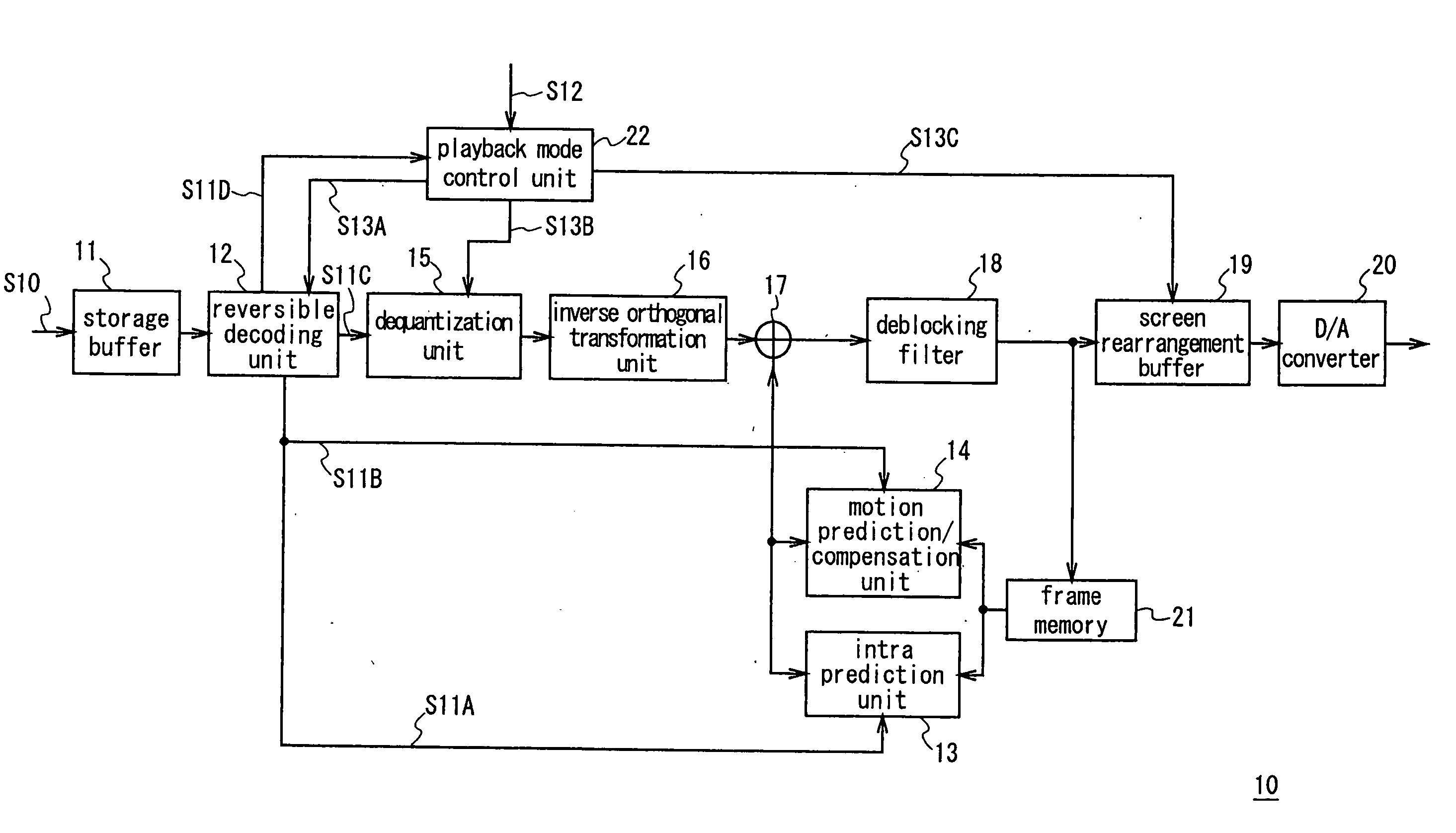
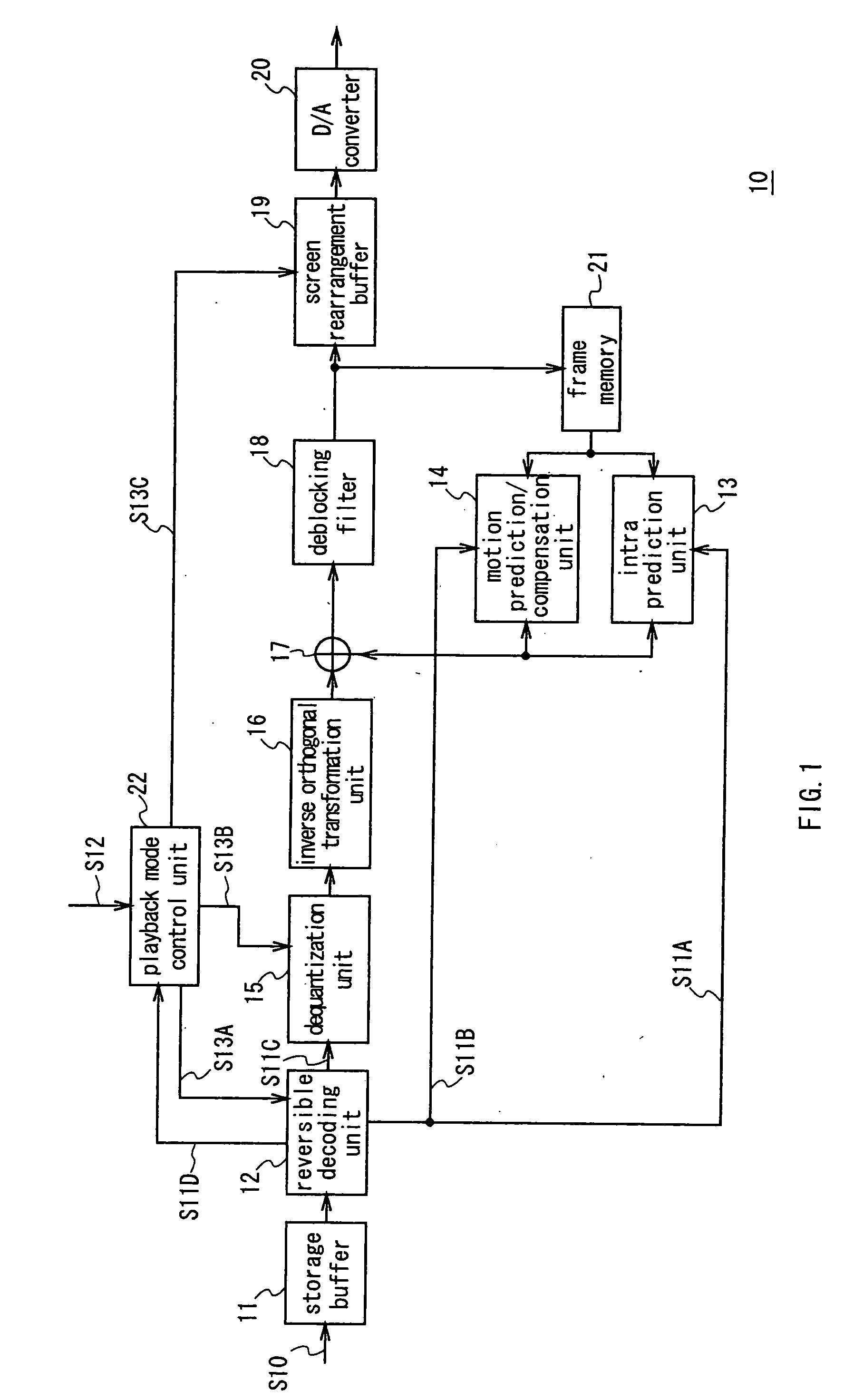
[0124] Referring to FIG. 1, reference numeral 10 shows an image decoding apparatus under the JVT coding method according to this embodiment. Picture compression information S10 comprising a bit stream externally input is restored into high fine pictures for display while being sequentially decoded according a playback mode externally specified.

[0125] The externally input picture compression information S10 is stored in a storage buffer 11, and then is read and sent to a reversible decoding unit 12 at prescribed timing. The reversible decoding unit 12 performs variable length decoding and arithmetic decoding according to the predetermined format of the picture compression information.

[0126] At this time, the reversible decoding unit 12 determines which coding metho...


PUM


Abstract

This invention realizes an image decoding apparatus and an image decoding method capable of correctly performing a decoding process in short time with a simple construction. In an image decoding apparatus and an image decoding method for performing a decoding process under a prescribed coding method, simple playback frames comprising an I-picture and following prescribed pieces of P-pictures on the basis of the I-picture existing at a desired position in picture data encoded with the coding method are extracted in a fast playback mode.

Description

TECHNICAL FIELD [0001] This invention relates to an image decoding apparatus and an image decoding method and, for example, is suitably applied to an image decoding apparatus and an image decoding method under the JVT (Joint Model of Enhanced-Compression Video Coding) scheme. BACKGROUND ART [0002] Recently, for both information distribution of broadcasting stations and information reception of general households, such apparatuses have been proposed that treat picture information by digitizing it, and operate under the MPEG (Moving Picture Experts Group) scheme or the like to compress the information through orthogonal transformation such as discrete cosine transformation, and motion compensation, with making use of redundancy of picture information, in order to realize efficient transmission and storage of the information. [0003] Specifically, the MPEG2 (ISO / IEC 13818-2) is defined as a general image coding method, and is widely used in various applications for professionals and con...

Claims


Application Information

Patent Timeline
Patent Type & Authority Applications(United States)
IPC IPC(8): G06K9/36H04N5/76H04N5/783H04N5/92H04N5/93H04N9/804H04N19/102H04N19/132H04N19/134H04N19/139H04N19/44H04N19/50H04N19/503H04N19/513H04N19/61H04N19/625H04N19/80H04N19/90
CPCH04N5/783H04N9/8042H04N19/587H04N19/44H04N19/132H04N5/93H04N19/51
Inventor NAGUMO, TAKEFUMIYAGASAKI, YOICHISUZUKI, TERUHIKO
Owner SONY CORP
Why Eureka
Try Eureka