Continuously variable transmission controller

a transmission controller and variable technology, applied in mechanical equipment, instruments, gearboxes, etc., can solve the problems of shifting shock, affecting the durability of the transmission, affecting the riding comfort of the vehicle, etc., and achieve the effect of reducing the shifting shock

Inactive Publication Date: 2007-01-04
HONDA MOTOR CO LTD
View PDF3 Cites 171 Cited by
  • Summary
  • Abstract
  • Description
  • Claims
  • Application Information

AI Technical Summary

Benefits of technology

[0008] An object of the present invention is to provide a continuously variable transmission controller which can reduce a shift shock generated when a shift characteristic is changed in a continuously variable transmission capable of changing the shift characteristic between drive modes of a vehicle.

Problems solved by technology

Such an arrangement causes a shift shock which may impair the riding comfort of the vehicle and affect the durability of the transmission.
A shift shock caused by a change in shift characteristic resulting from a drive mode change, however, cannot be adequately reduced just by adjusting the duty of the motor according to a difference between pulley ratios.

Method used


Image

  • Continuously variable transmission controller
  • Continuously variable transmission controller
  • Continuously variable transmission controller

Examples


Embodiment Construction

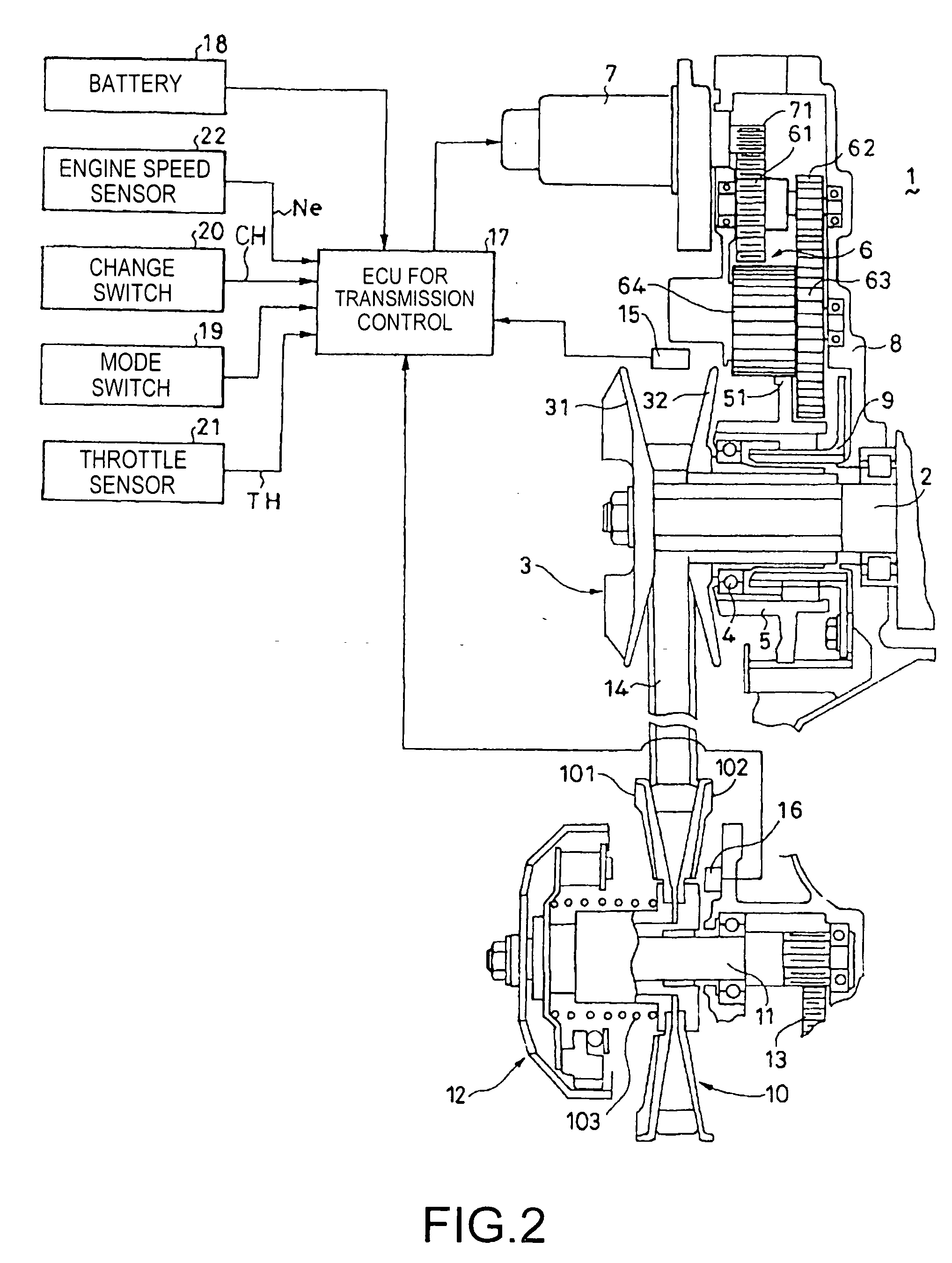
[0030] An embodiment of the present invention will be described in the following with reference to the accompanying drawings. FIG. 2 is a diagram showing a system configuration of a continuously variable transmission controller according to an embodiment of the present invention. A continuously variable transmission 1 is connected to a crankshaft, that is, an output shaft 2, of an engine (not shown) used as a drive source, for example, for an all terrain vehicle (ATV). A drive pulley 3 includes a fixed pulley piece 31 and a movable pulley piece 32 which is mounted on the output shaft 2 to be slidable along the axial direction of the output shaft 2. A slider 5 is supported on a periphery of a hub of the movable pulley piece 32 via a bearing 4. A gear 51 is formed on a periphery of the slider 5. The gear 51 engages with a final stage gear 64 of a speed reducer 6 comprising four gears 61 to 64. The first stage gear 61 of the speed reducer 6 engages with an output gear 71 of a motor 7. ...


PUM


Abstract

A continuously variable transmission is mounted on a vehicle capable of selecting plural drive modes and changes a target engine speed between drive modes. A pulley ratio is controlled by a motor. An ECU for transmission control includes a calculation section which outputs a target engine speed as a function of throttle opening and vehicle speed, and a motor control value determination section which outputs a control value for controlling the motor based on the target engine speed and an actual engine speed. In a case where, when a drive mode is selected, the current target engine speed changes by an amount exceeding a predetermined judgment value according to vehicle speed, the motor control value determination section updates the current target engine speed in a stepwise manner. The resulting configuration reduces a shift shock caused by a drive mode change.

Description

CROSS-REFERENCE TO RELATED APPLICATION [0001] The present application claims priority under 35 U.S.C. §119 to Japanese Patent Application No. 2005-191626, filed Jun. 30, 2006, the entire contents of which are hereby incorporated by reference. BACKGROUND OF THE INVENTION [0002] 1. Field of the Invention [0003] The present invention relates to a continuously variable transmission controller, and more particularly, to a continuously variable transmission controller suitable for reducing a shift shock generated when a drive mode is changed causing a shift characteristic to largely change. [0004] 2. Description of Background Art [0005] A controller (See, for example, JP-A No. 123351 / 1994) for a belt-type continuously variable transmission connected to an internal-combustion engine (hereinafter referred to as an “engine”) has been known in which a pulley ratio is controlled by, using a motor, sliding a movable side of a drive pulley along an output shaft of the engine. In the controller, ...

Claims


Application Information

Patent Timeline
Patent Type & Authority Applications(United States)
IPC IPC(8): B60W10/04
CPCB60W10/06B60W10/107B60W30/182Y10T477/6242F16H61/66254F16H2300/14Y10T477/619B60W30/19F16H63/00F16H59/24F16H9/00
Inventor MATSUDAIRA, NAOTADAASUMI, MICHIO
Owner HONDA MOTOR CO LTD
Why Eureka
Try Eureka