Probing method and holding method for lumenal organ

a holding method and lumenal organ technology, applied in the field of holding methods for lumenal organs, can solve the problems of not being able to continue surgery, leaving all or part of the lesion behind after resection,

Active Publication Date: 2007-01-04
OLYMPUS CORP
View PDF9 Cites 40 Cited by
  • Summary
  • Abstract
  • Description
  • Claims
  • Application Information

AI Technical Summary

Problems solved by technology

If the needle penetrates through the stomach wall, then not only does the site of the lesion become unclear, but other internal organs may become coated with the India ink, resulting in a situation in which it is not possible to continue with surgery.
Further, if the India ink cannot be injected so as to be visible from outside the stomach, then it is not possible to discern the lesion site, which can result in the all or part of the lesion being left behind following resection.
In other words, the problem with this dot inking method is that it requires a high level of expertise to adjust the depth to which the needle is pierced, so that the dot inking can be carried out reliably.

Method used


Image

  • Probing method and holding method for lumenal organ
  • Probing method and holding method for lumenal organ
  • Probing method and holding method for lumenal organ

Examples


embodiment 1

(Embodiment 1)

[0028] The surgery to partially resect the stomach under laparoscopy will be explained in this embodiment with reference to FIGS. 1 through 9.

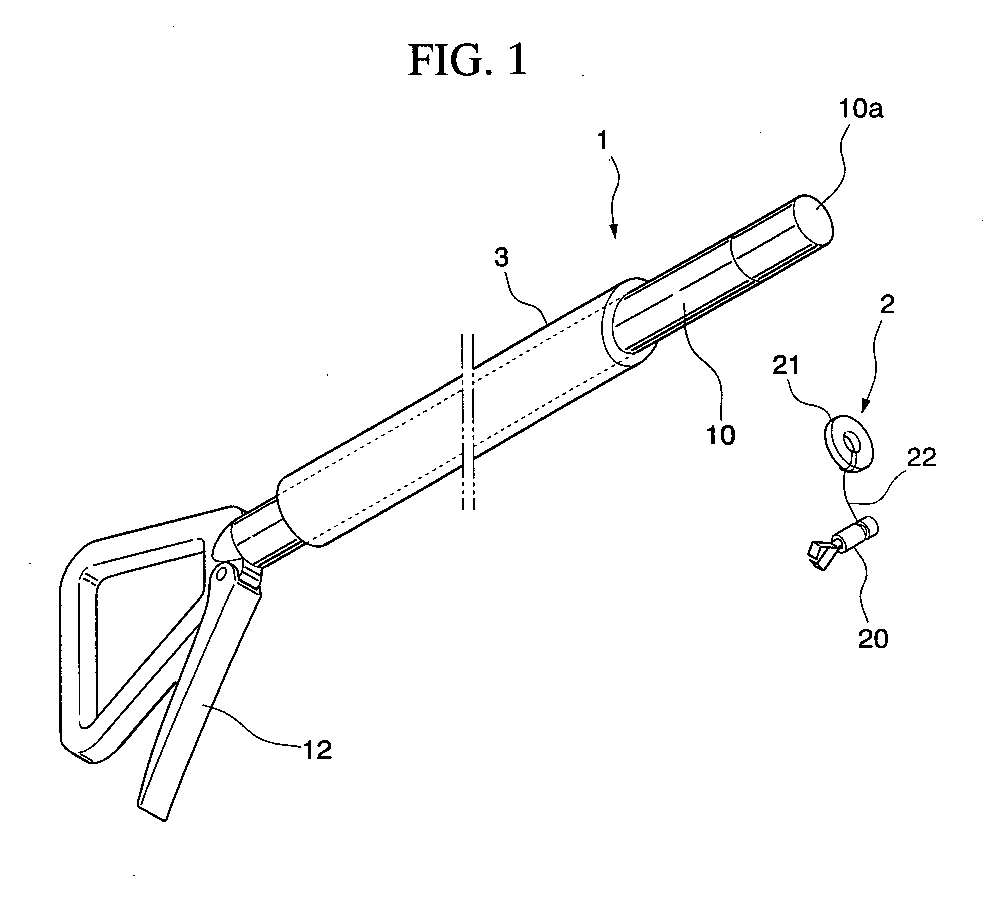
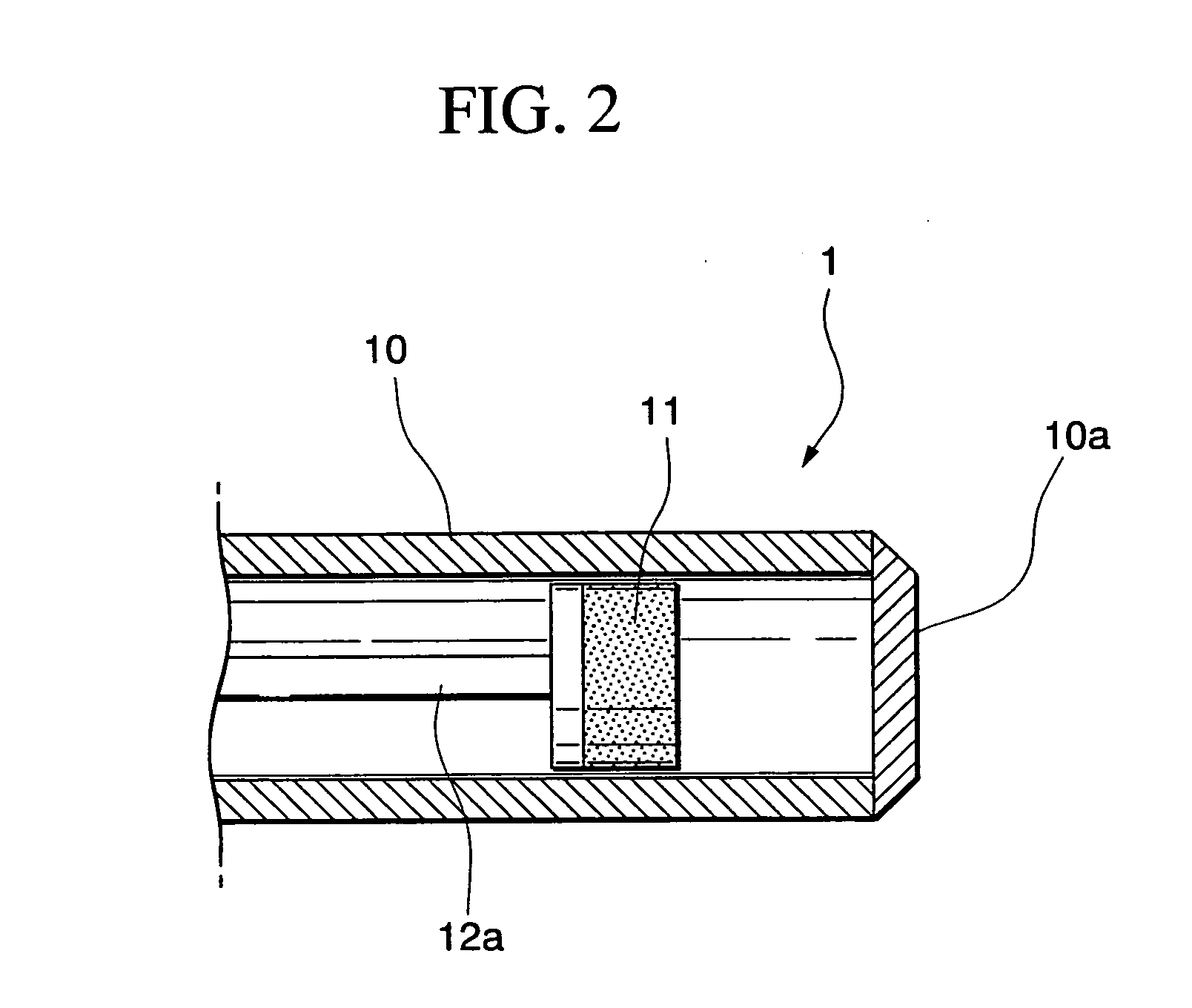
[0029] The instruments employed in the surgery will be explained first. FIGS. 1 and 2 show a magnetic forceps 1 and an anchoring device 2, which is anchored on the inside of the stomach, that are employed in the partial resection of the stomach in this embodiment. Magnetic forceps 1 is provided with an inserted part 10 which is inserted into the abdominal cavity, a magnet 11 for attracting and adsorbing anchoring device 2, and an operating part 12 for operating magnet 11. Inserted part 10 is in the form of a rigid narrow tube, the end of which is covered by fixing in place a cover 10a.

[0030] Magnet 11 is cylindrical in shape and has an outer diameter that is slightly smaller than the inner diameter of inserted part 10. One end surface thereof forms the N pole, and the other end surface thereof forms the S pole. The magnetic lin...

embodiment 2

(Embodiment 2)

[0050] In this embodiment, the surgery for partial resection of the large intestine will be explained with reference to FIGS. 10 through 13.

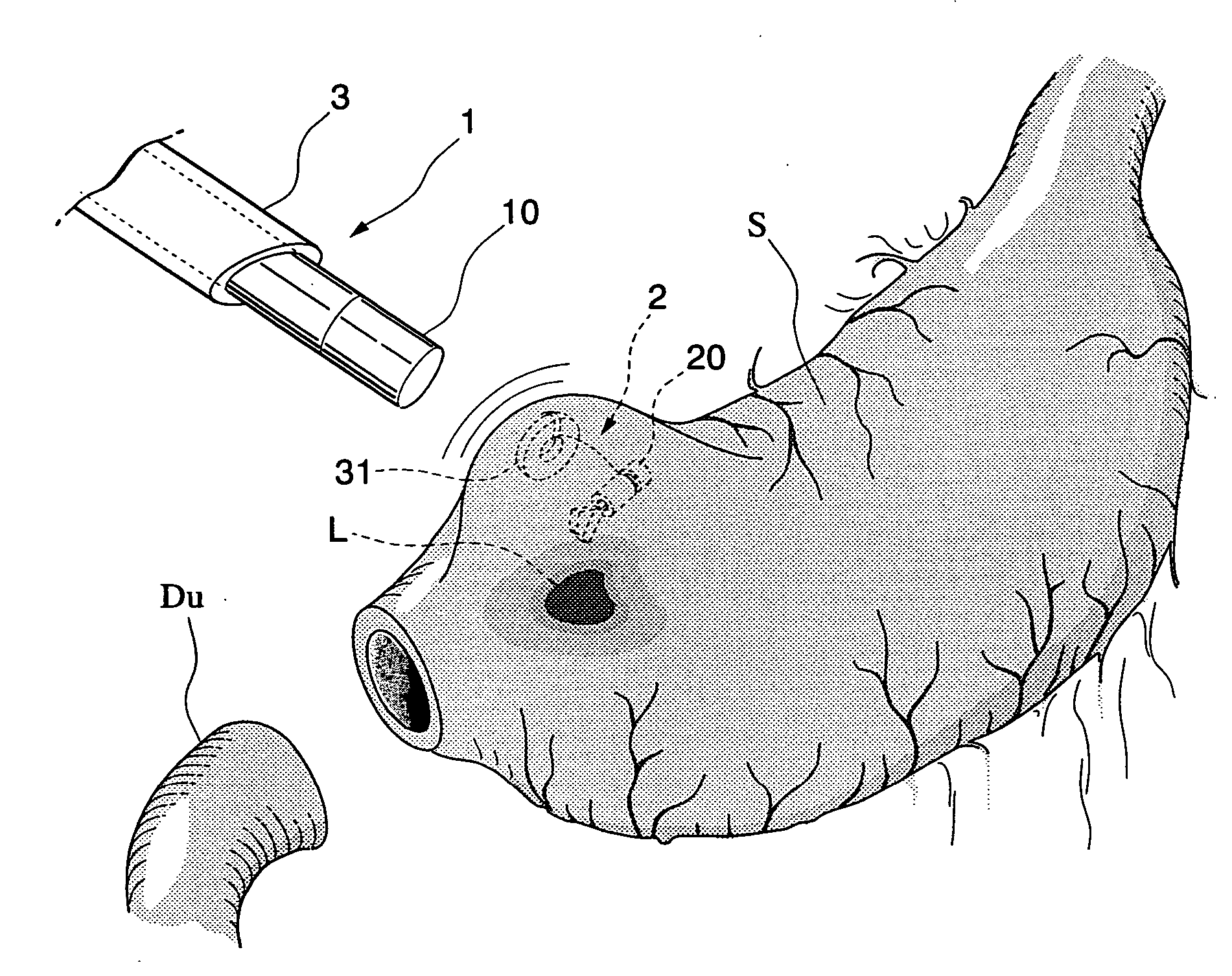
[0051] First, several days to several weeks prior to the surgery, anchoring device 2 is anchored in the intestinal wall near the site where a lesion has occurred on the inside of the large intestine. Specifically, an endoscope is inserted via the anus, anchoring device 2 is introduced to the inside of the large intestine by passing it through the inserted part of the endoscope, and the intestinal wall near the lesion site is grabbed and held by clip 20. In order to prevent clip 20 from falling off, care is exercised to ensure that clip 20 firmly grabs the mucosa of the intestinal wall. Further, in order to appropriately resect the lesion during surgery, the positional relationship between the lesion site and the site where anchoring device 2 is anchored is recognized.

[0052] Next, the actual surgical sequence will be explained.

[0...


PUM


Abstract

The present invention enables the desired area on a luminal organ to be held correctly during laparotomy or laparoscopic surgery, even without carrying out dot inking which requires a high degree of skill. In the present invention, a magnetic body is pre-anchored at a specific position inside a luminal organ. During surgery, a magnet is brought close to the outside of the luminal organ, such that the magnetic body is adsorbed to the magnet, along with the body tissue of the luminal organ, enabling traction.

Description

BACKGROUND OF THE INVENTION [0001] 1. Field of the Invention [0002] The present invention relates to a method for probing a specific site on the inner surface of a luminal organ within a body cavity, and to a method for holding the same luminal organ, during laparotomy or laparoscopic surgery. [0003] 2. Description of Related Art [0004] A dot inking method employing India ink is carried out as a method for identifying microscopic lesions occurring on the inside of a luminal organ, such as the stomach or large intestine, during surgery via laparoscopy or laparotomy. In this dot inking method, India ink, which serves as a marker near the lesion, is injected from inside the luminal organ, to facilitate identification of the location of the lesion during either direct or indirect gross visualization of the outside of the luminal organ. A surgical method in which a lesion site occurring on the inside of the stomach is resected will now be explained as one example of this dot inking metho...

Claims


Application Information

Patent Timeline
Patent Type & Authority Applications(United States)
IPC IPC(8): A61N2/00
CPCA61B17/02A61B17/0281A61B2019/5454A61B2017/00876A61B2019/5404A61B17/22031A61B2090/3904A61B2090/3954
Inventor OHDAIRA, TAKESHI
Owner OLYMPUS CORP
Why Eureka
Try Eureka