Eureka AIR delivers breakthrough ideas for toughest innovation challenges, trusted by R&D personnel around the world.

Glass run

a technology of glass run and run plate, which is applied in the direction of door/window fittings, transportation and packaging, wing accessories, etc., can solve the problems of insufficient sealing properties, and achieve the effects of good weathering resistance, good adhesion properties, and easy molding

Inactive Publication Date: 2007-01-11
TOYODA GOSEI CO LTD +1
View PDF10 Cites 23 Cited by
  • Summary
  • Abstract
  • Description
  • Claims
  • Application Information

AI Technical Summary

Benefits of technology

[0039] According to the fifth aspect of the invention, a good adhesion property can be provided between the corner portion and each extruded portion. In addition, since both the materials are olefin-based materials, a good weathering resistance can be provided, and since both the materials can be ground, a product obtained therefrom can be recycled. Since the corner portion is formed from the olefin-based thermoplastic elastomer, no vulcanization is necessary, resulting in easy molding.
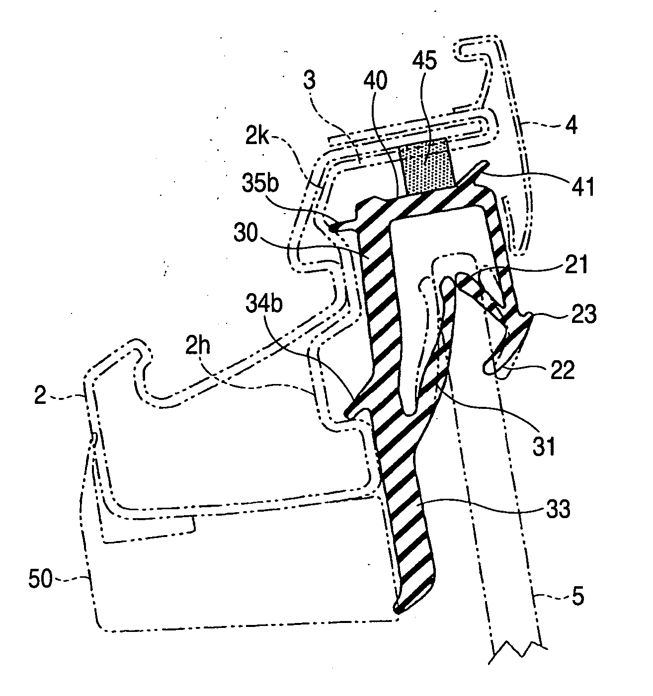
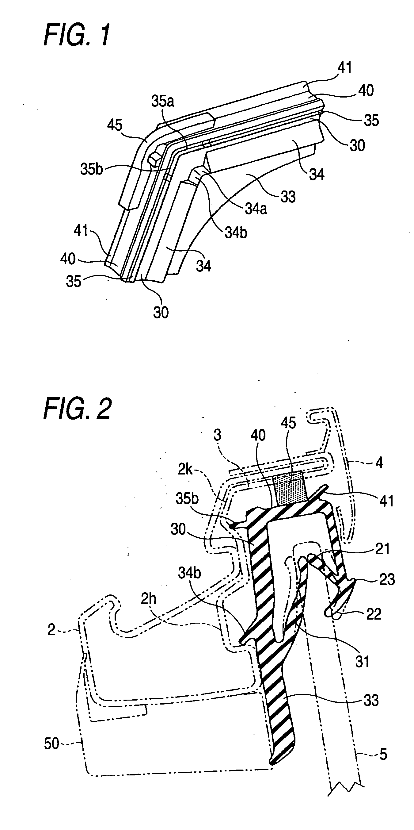
[0040] According to the invention, since the molded interior holding lip formed into substantially the L-shape as viewed from the front is formed on the corner portion and the end of the molded interior holding lip so formed is made to continue to the interior holding lips which lie to the vertical side portion and the upper side portion of the door frame, respectively, no gap is produced on the interior holding lip, and hence, the glass run can be brought into abutment with the door frame assuredly, thereby making it possible to increase the sealing property.
[0041] In addition, since the rigidity of the molded interior holding lips on the corner portion is made smaller than the rigidity of the interior holding lips on the extruded portions, when the glass run is attempted to be mounted on the door frame, the flexibility of the interior holding lip on the corner portion becomes high at the corner portion of the glass run, and hence, the glass run can easily be mounted on the door frame.

Problems solved by technology

In addition, in the event that the seal lip is simply reduced in thickness while maintaining the same shape as that of the holding lips, the sealing property becomes insufficient.

Method used


Image

  • Glass run
  • Glass run
  • Glass run

Examples


Embodiment Construction

[0048] An embodiment of the invention will be described based on FIGS. 1 to 5.

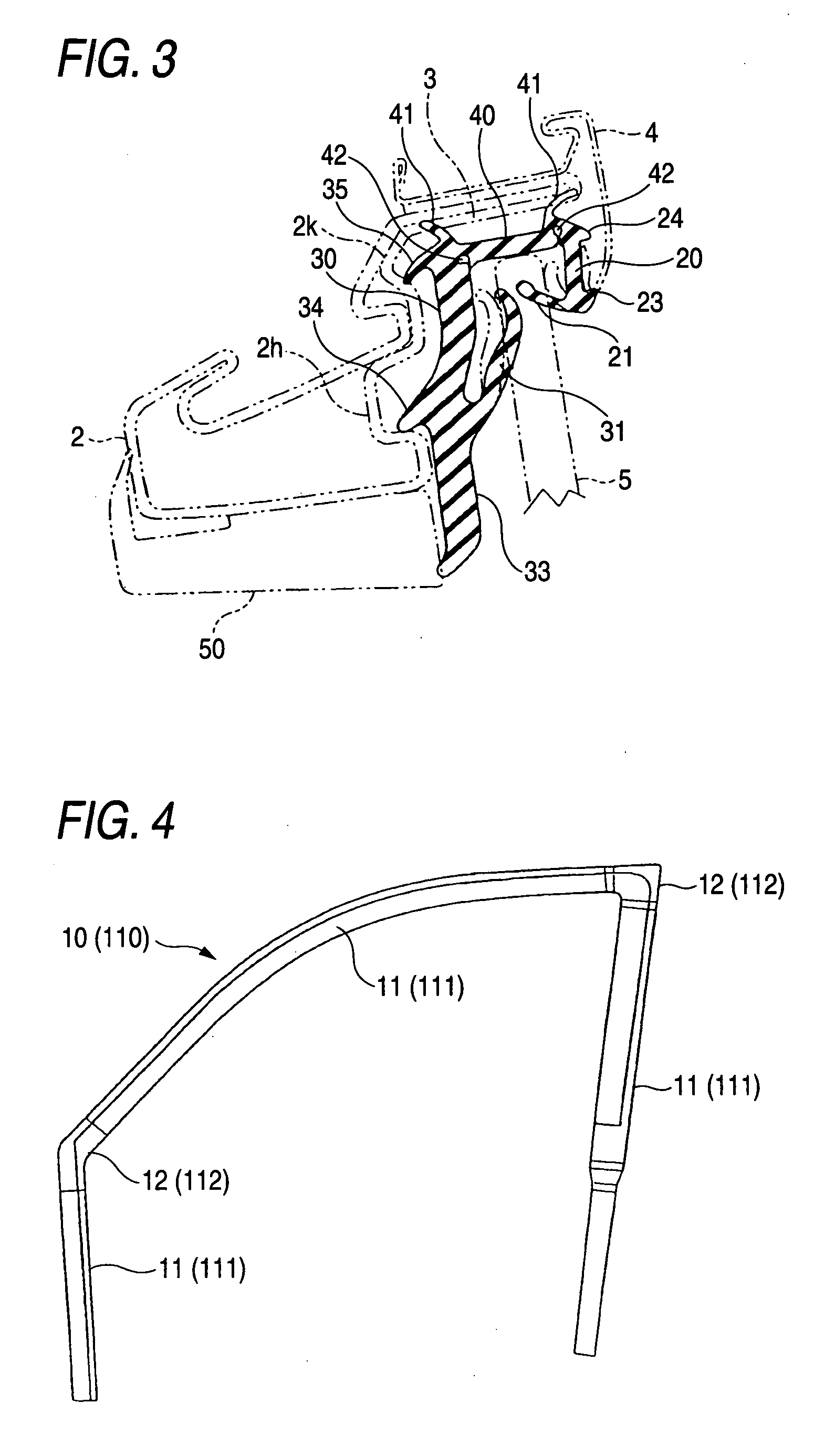
[0049]FIG. 5 is a front view of a front side door 1 of a motor vehicle, and FIG. 4 is a front view of a front side door glass run 10 that is to be mounted on a door frame or a door frame, as a matter of fact, of the door 1. As shown in FIG. 5, the door frame 2 is provided at an upper portion of the door 1, and a window glass 5 is mounted in the door frame 2 in such a manner as to move up and down therein. Namely, the glass run 10 is mounted along an inner part of the door frame 2 so as to guide the window glass 5 moving up and down, as well as establish a seal between the window glass 5 and the door frame 2.

[0050] As shown in FIG. 4, the glass run 10 is, as a whole, provided with extruded portions 11 which are extruded and corner portions 12 which are molded to connect the extruded portions 11 together and are mounted on corner portions of the door frame 2.

[0051] The extruded portions 11 are a portion t...


PUM


Abstract

A glass run is provided in which a main body of a glass run is provided with an exterior side wall, an interior side wall and a bottom wall, an interior holding lip to be locked in a recess on a door frame is provided on an external surface of each interior side wall of extruded portions of the glass run, while interior holding lips on the corner portions are formed in substantially an L-shape to be angled to match the corner portion such that a distal end of the interior holding lip continues to an interior holding lip on a vertical side portion whereas a distal end of the other interior holding lip continues to an interior holding lip on an upper side portion, and the rigidity of the interior holding lips on the corner portion is made smaller than the interior holding lips on the extruded portions.

Description

BACKGROUND OF THE INVENTION [0001] 1. Field of the Invention [0002] The present invention relates to a glass run which is mounted along an inner part of a door frame of a vehicle door and which has extruded portions which guide a window glass which moves up and down and corner portions. [0003] 2. Related Art [0004] As shown in FIG. 5, a glass run 110 which guides a window glass moving up and down is mounted along an inner part of a door frame 2 of a vehicle door 1. A corner portion of the conventional glass run 110 is shown in FIG. 6. FIG. 6 is a perspective view of the corner portion of the glass run 110 which is to lie at a portion corresponding to a corner portion of the door frame 2 which is formed between an upper side portion and a rear vertical side portion of the door frame 2. [0005] Conventionally, the glass run 110 is, as shown in FIG. 5, mounted in a channel 3 of the door frame 2 to form a seal between the window glass 5 and the door frame 2 as well as guide the window gl...

Claims


Application Information

Patent Timeline
Patent Type & Authority Applications(United States)
IPC IPC(8): E06B7/16
CPCB60J10/0017B60J10/04B60J10/0062B60J10/21B60J10/30B60J10/74
Inventor HIRAMATSU, TAKAYOSHIOKAJIMA, TERUYUKIMIO, SATOSHI
Owner TOYODA GOSEI CO LTD
Why Eureka
Eureka Blog
Learn More