Double lip dust excluder fork seal

a technology of dust excluder and fork seal, which is applied in the field of seals, can solve the problems of loss of lip force, inability to utilize the full wear life of the original interference, and springs exposed to the environmen

Inactive Publication Date: 2007-01-11
CLARK SEALS
View PDF8 Cites 15 Cited by
  • Summary
  • Abstract
  • Description
  • Claims
  • Application Information

AI Technical Summary

Benefits of technology

[0009] In the preferred embodiment, the dust seal is comprised of two sealing lips all shaped and arranged to seal in one direction. The air side of the seal has a excluder lip properly positioned to initially prevent dirt and debris from entering the fork cavity. The second internal sprung excluder lip rotates the lip contact point toward the air side and thereby providing a double lip sealing arrangement. The invention thus provides a greatly improved excluder sealing capable of withstanding the repetitious and extreme environment imposed on the shock absorbers comprising the front wheel forks of cycles, and providing a long seal service life.

Problems solved by technology

In all current fork seal dust lip designs with garter springs the springs are exposed to the environment and become fouled by dirt and debris.
The stress relaxation results in a loss of lip force that does not allow the seal to utilize the full wear life of the original interference.

Method used


Image

  • Double lip dust excluder fork seal
  • Double lip dust excluder fork seal
  • Double lip dust excluder fork seal

Examples


Embodiment Construction

[0014] The embodiments discussed herein are merely illustrative of specific manners in which to make and use the invention and are not to be interpreted as limiting the scope of the instant invention.

[0015] While the invention has been described with a certain degree of particularity, it is to be noted that many modifications may be made in the details of the invention's construction and the arrangement of its components without departing from the spirit and scope of this disclosure. It is understood that the invention is not limited to the embodiments set forth herein for purposes of exemplification.

[0016] The following is a detailed description of an embodiment of the invention presently contemplated by the inventor to be the best mode of carrying out his invention.

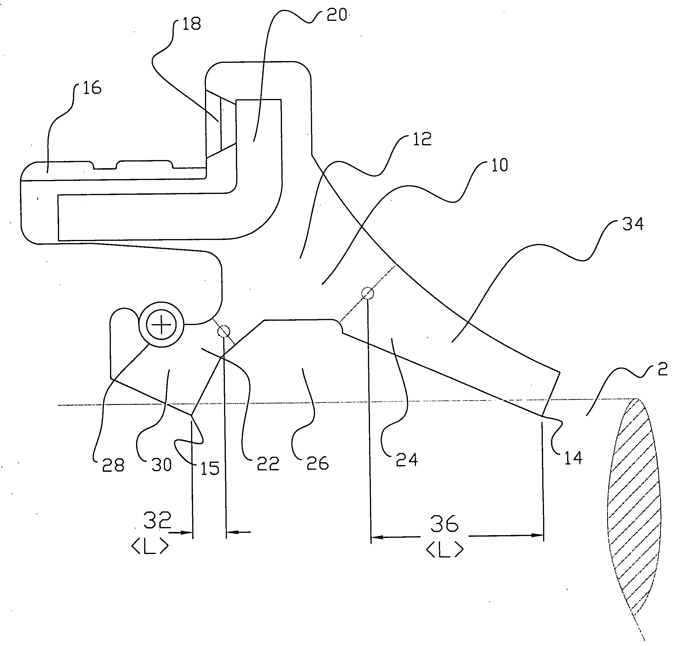
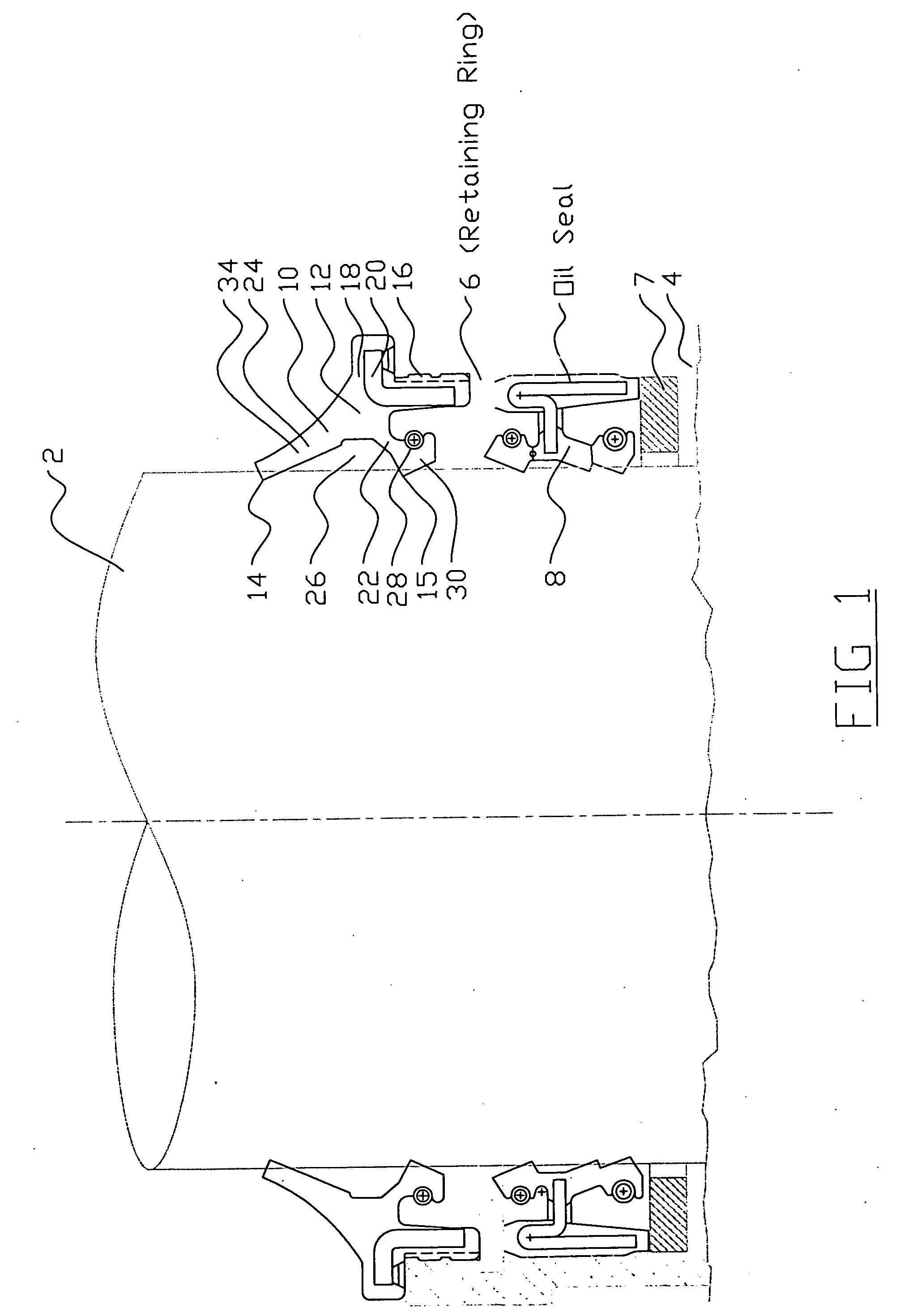
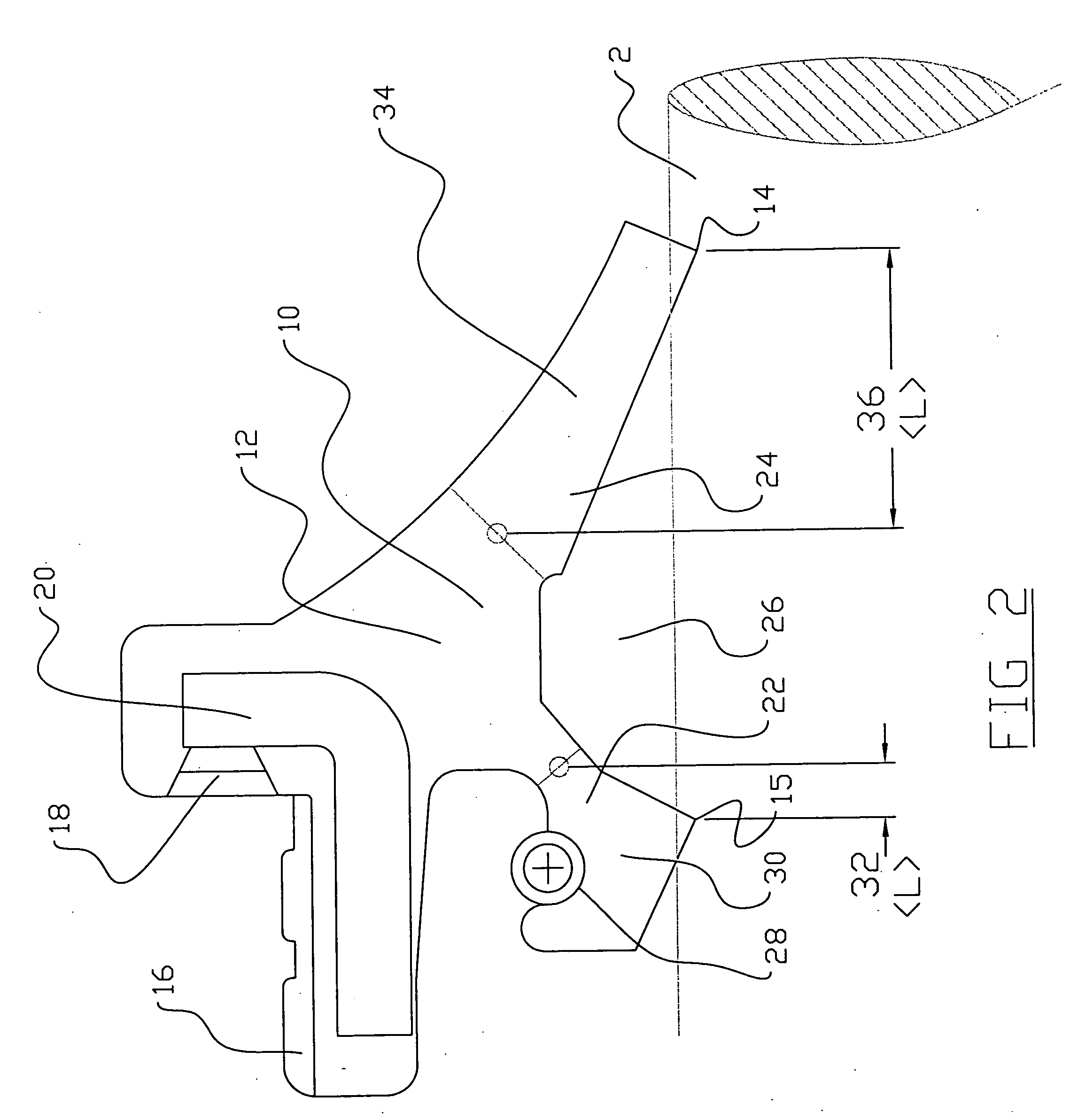
[0017]FIG. 1 illustrates a portion of an inner cylinder shaft or tube 2 which moves axially with respect to an outer cylindrical tube 4 (seen in cross-section in FIG. 1). A dust excluder seal 10 of the present invent...


PUM


Abstract

A double lip seal for a dust excluder seal for a cylindrical reciprocating tube connected to a recreational or utility vehicle, wheel and an off-road motorcycle or bicycle. The seal includes an oil side beam generally parallel to the axis of the reciprocating members and having a spring loaded dust excluder lip for engaging the inner cylindrical tube and wherein the spring is protected from dust and dirt by an outer excluder lip that prevents the garter sprung lip from fouling. In addition the lip is designed with a negative R-value which allows the sprung lip to rotate and position the geometry of the lip to act as a dust excluder lip. The protected spring can now compensate for lip wear which enhances the service life of the seal. The seal also includes an air side beam having a second sealing lip engaging the inner cylindrical tube.

Description

BACKGROUND OF THE INVENTION [0001] 1. Field of the Invention [0002] The present invention relates to seals for a set of reciprocating parts, and more particularly, to seals for shock absorbers which absorb mechanical vibration from road impacts comprising a front wheel suspension of recreational vehicles, such as motorcycles, bicycles and the like. [0003] 2. Prior Art [0004] Motorcycles and many bicycles, especially off-road cycles or bikes, have front wheel suspension fork assemblies which include a pair of spaced parallel shock absorbers. Each shock absorber typically comprises a compression spring, an inner tube or shaft connected to the axle of the front wheel and a co-axial, oil-filled outer tube or cylinder connected to the frame of the vehicle and within which the shaft is reciprocable to absorb shocks imparted to the front wheel. Two or more seals are required between the shaft and cylinder for preventing leakage of oil from the cylinder and for preventing entry of air, mois...

Claims


Application Information

Patent Timeline
Patent Type & Authority Applications(United States)
IPC IPC(8): F16J15/32
CPCF16J15/3252F16J15/3232
Inventor ZAHN, HENRY W.
Owner CLARK SEALS
Why Eureka
Try Eureka