Power supply device and image forming apparatus using the power supply device

a technology of power supply device and power supply device, which is applied in the direction of generator/motor, electrographic process, instruments, etc., can solve the problems of long rise time of high voltage output, delay of sweep time of frequency, and difficulty in reducing the size and weight of the whole apparatus, so as to shorten the rise time of high voltage

Inactive Publication Date: 2007-01-11
CANON KK
View PDF14 Cites 11 Cited by
  • Summary
  • Abstract
  • Description
  • Claims
  • Application Information

AI Technical Summary

Benefits of technology

[0014] Embodiments of the present invention provide a power supply device that enables shortening of a rise time of high voltage and an image forming apparatus that employs the power supply device.

Problems solved by technology

Thus, if winding electromagnetic transformers are used, it is difficult to achieve reduction in size and weight of the whole apparatus.
This delays the sweep time of frequency and the rise time of a high voltage output becomes longer.

Method used


Image

  • Power supply device and image forming apparatus using the power supply device
  • Power supply device and image forming apparatus using the power supply device
  • Power supply device and image forming apparatus using the power supply device

Examples


first exemplary embodiment

[0043] First Exemplary Embodiment

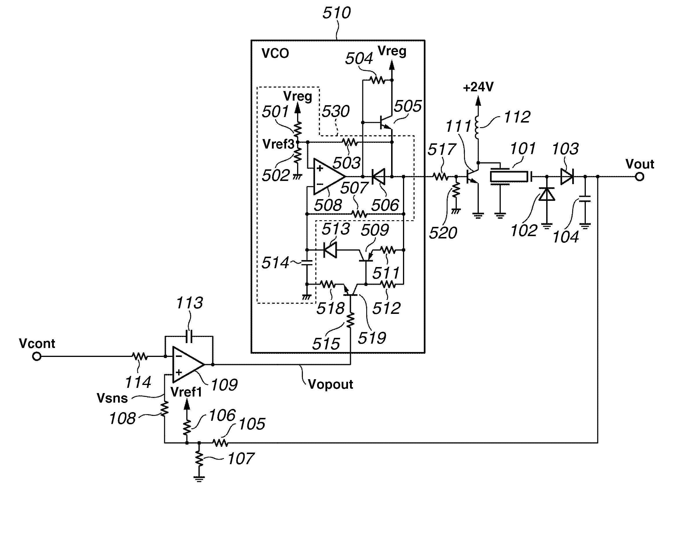
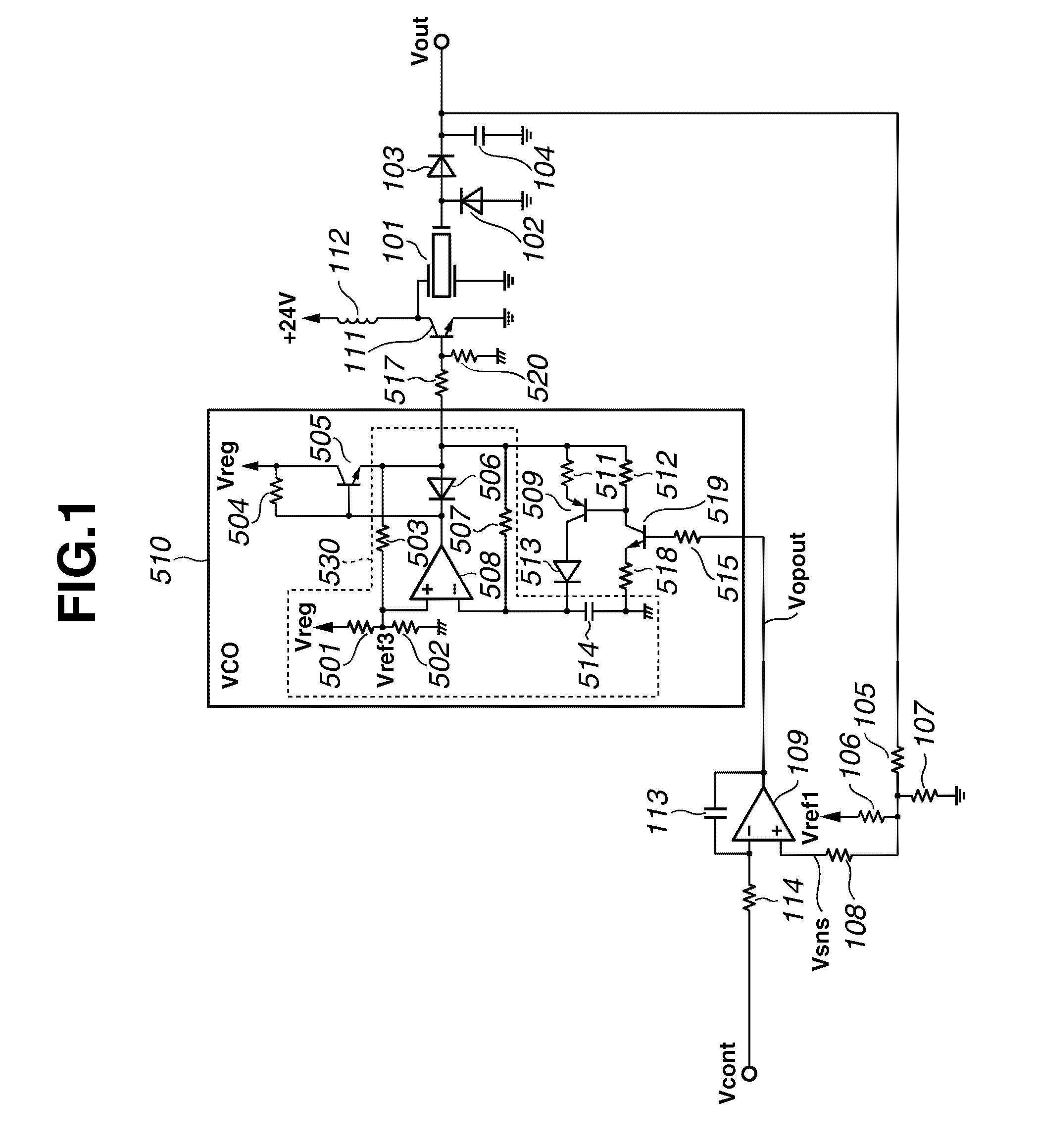
[0044]FIG. 1 is a diagram showing a high voltage power supply circuit of the piezoelectric transformer type employed in the high voltage power supply unit 202 according to a first exemplary embodiment of the present invention. In FIG. 1, Reference numeral 101 denotes the piezoelectric transformer (piezoelectric ceramic transformer), Reference numerals 102, 103, 506, and 513 denote diodes, and Reference numerals 104, 113, and 514 denote capacitors. Reference numerals 105-108, 114, 501-504, 507, 511, 512, 515, 517, 518, and 520 denote resistors, Reference numeral 109 denotes an operational amplifier, and Reference numerals 111, 505, 509, and 519 denote transistors. Reference numeral 112 denotes an inductor, Reference numeral 508 denotes a comparator, Reference numeral 510 denotes a voltage controlled oscillator (VCO), and Reference numeral 530 denotes a CR oscillating circuit.

[0045] Output of the piezoelectric transformer 101 is rectified and smoothed...

second exemplary embodiment

[0057] Second Exemplary Embodiment

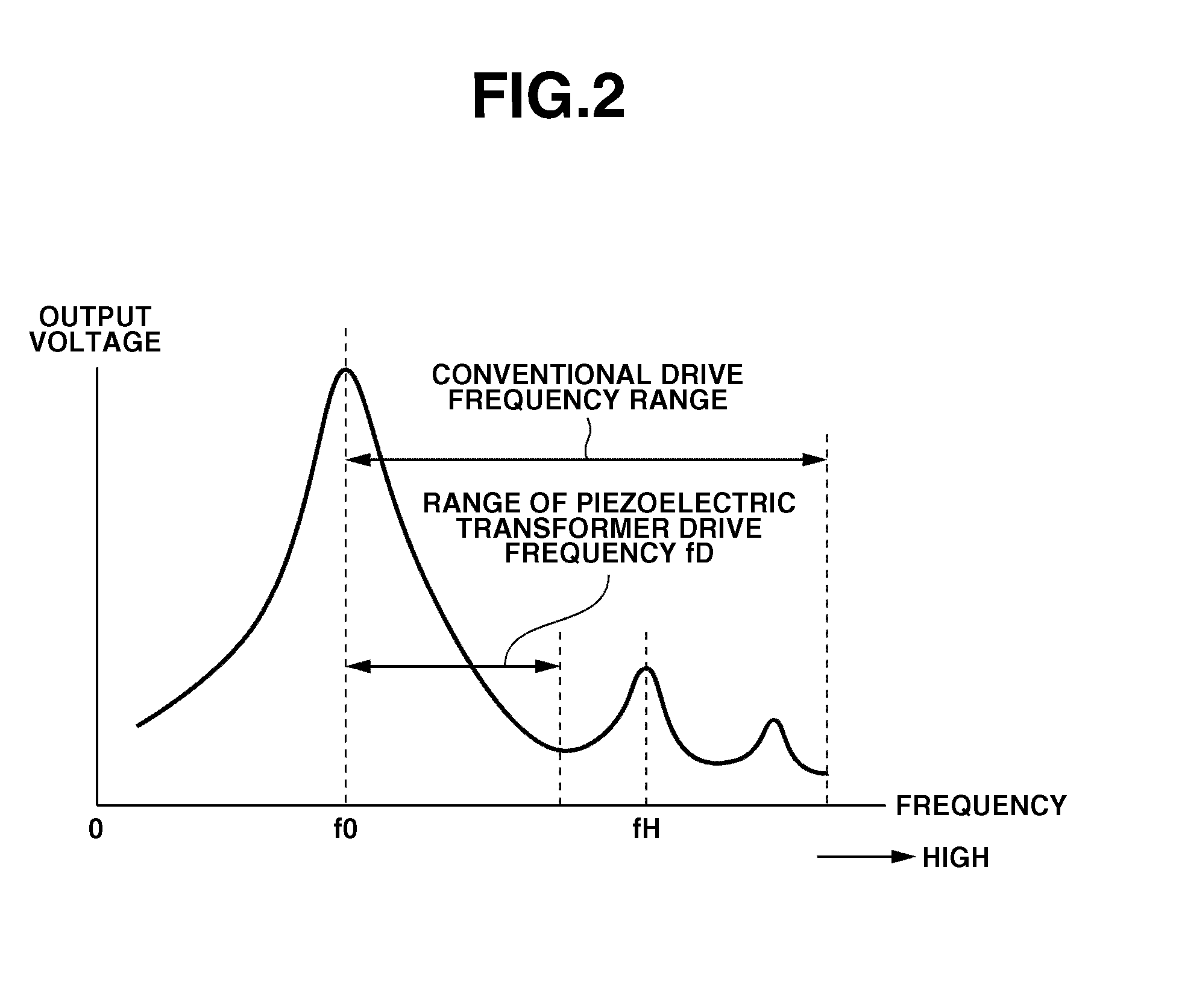
[0058] A main difference of the second exemplary embodiment from the first exemplary embodiment is to set the range of the drive frequency fD of the piezoelectric transformer 101 to be on the frequency side that is lower than the resonant frequency f0 of the piezoelectric ceramic vibration body.

[0059]FIG. 4 is a diagram showing a high voltage power supply circuit of the piezoelectric transformer type according to the second exemplary embodiment of the present invention.

[0060] The circuit illustrated in FIG. 4 includes a push-pull circuit configured by transistors 505 and 521 without using the transistor 111 and inductor 112 in FIG. 1 of the first exemplary embodiment. The piezoelectric transformer is pulse-driven directly by a source voltage via a resistor 522.

[0061] According to the second exemplary embodiment, the piezoelectric transformer 101 is driven in the frequency range on the lower frequency side of the resonant frequency f0. In contrast...

third exemplary embodiment

[0068] Third Exemplary Embodiment

[0069] According to the first or second exemplary embodiment, the piezoelectric transformer 101 operates even if the control signal Vcont is 0 V, and a micro output voltage Vcont is maintained. Therefore, the output voltage Vout will not become completely 0 V. Consequently, a voltage is always applied to process members such as photoreceptors and transfer rollers of an electrophotographic printer. This state shortens a life of process members. It is also a problem that power is uselessly consumed due to a continuous operation of the piezoelectric transformer 101.

[0070] Thus, in the configurations described in the first or second exemplary embodiment, the output voltage Vout is set completely to 0 V according to the third exemplary embodiment when the output voltage Vout falls to a prescribed voltage below the output voltage used for image forming operations.

[0071] The third exemplary embodiment is applicable to both configurations in which the piez...


PUM


Abstract

A power supply device generates an output voltage by driving a piezoelectric transformer using a frequency signal. The power supply device includes a comparison unit configured to compare an output voltage and a voltage setting signal that sets the output voltage, and a voltage control oscillation unit configured to generate the frequency signal to drive the piezoelectric transformer based on comparison results of the comparison unit. The voltage control oscillation unit generates the frequency signal within a range between the resonant frequency and a spurious resonant frequency closest to the resonant frequency.

Description

BACKGROUND OF THE INVENTION [0001] 1. Field of the Invention [0002] The present invention relates to a power supply device, for example, for an image forming apparatus using an electrophotographic process, and an image forming apparatus using the power supply device. [0003] 2. Description of the Related Art [0004] In the technology of an electrophotographic printer, a direct transfer method is known in which a transfer roller is brought into contact with a photoreceptor and an image is transferred onto a record sheet inserted between the photoreceptor and the transfer roller. In this case, roller-shaped conductive rubber having a conductive axis is used as the transfer roller and the roller is driven corresponding to a process speed of the photoreceptor. Then, a direct bias voltage is applied to the transfer roller. Polarities of the direct bias voltage are the same as those of a normal corona discharge transfer voltage. However, to obtain excellent transfer when using such a transf...

Claims


Application Information

Patent Timeline
Patent Type & Authority Applications(United States)
IPC IPC(8): H01L41/09
CPCH01L41/044G03G15/80H10N30/804
Inventor MURATA, HIROKINAMIKI, TERUHIKONAGASAKI, OSAMUYAMAGUCHI, ATSUHIKONAKAMORI, TOMOHIROUCHIYAMA, TAKEHIROYASUKAWA, KOUJI
Owner CANON KK
Why Eureka
Try Eureka