Micro magnetic proximity sensor

a proximity sensor and micro-magnetic technology, applied in the field ofproximity sensors, can solve the problems of increasing costs, preventing the use of conventional microelectronic packaging techniques, and complicating fabrication processes, and achieve the effect of convenient fabrication and us

Inactive Publication Date: 2007-01-11
SCHNEIDER ELECTRIC IND SAS
View PDF17 Cites 3 Cited by
  • Summary
  • Abstract
  • Description
  • Claims
  • Application Information

AI Technical Summary

Benefits of technology

[0014] A micro magnetic proximity sensor is provided that is versatile and can be used in a variety of applications with only slight modification, that is relatively easy to fabricate and use, that

Problems solved by technology

Often this precludes the use of conventional microelectronic packaging techniques for MEMS devices, or requires that these techniques be modified.
Such packaging considerations can complicate fabrication processes and increase costs.
Thus, such switches are characterized as having only a single stable position (i.e., the quiescent state) and lack a latching capability (i.e., they do not retain a given position when power has been removed from the electromagnet).
Furthermore, the spring required to restore the cantilever to its quiescent position can degrade or break over time.
Thus, the electromagnet must consume power to maintain the cantilever in at leas

Method used


Image

  • Micro magnetic proximity sensor
  • Micro magnetic proximity sensor
  • Micro magnetic proximity sensor

Examples


Embodiment Construction

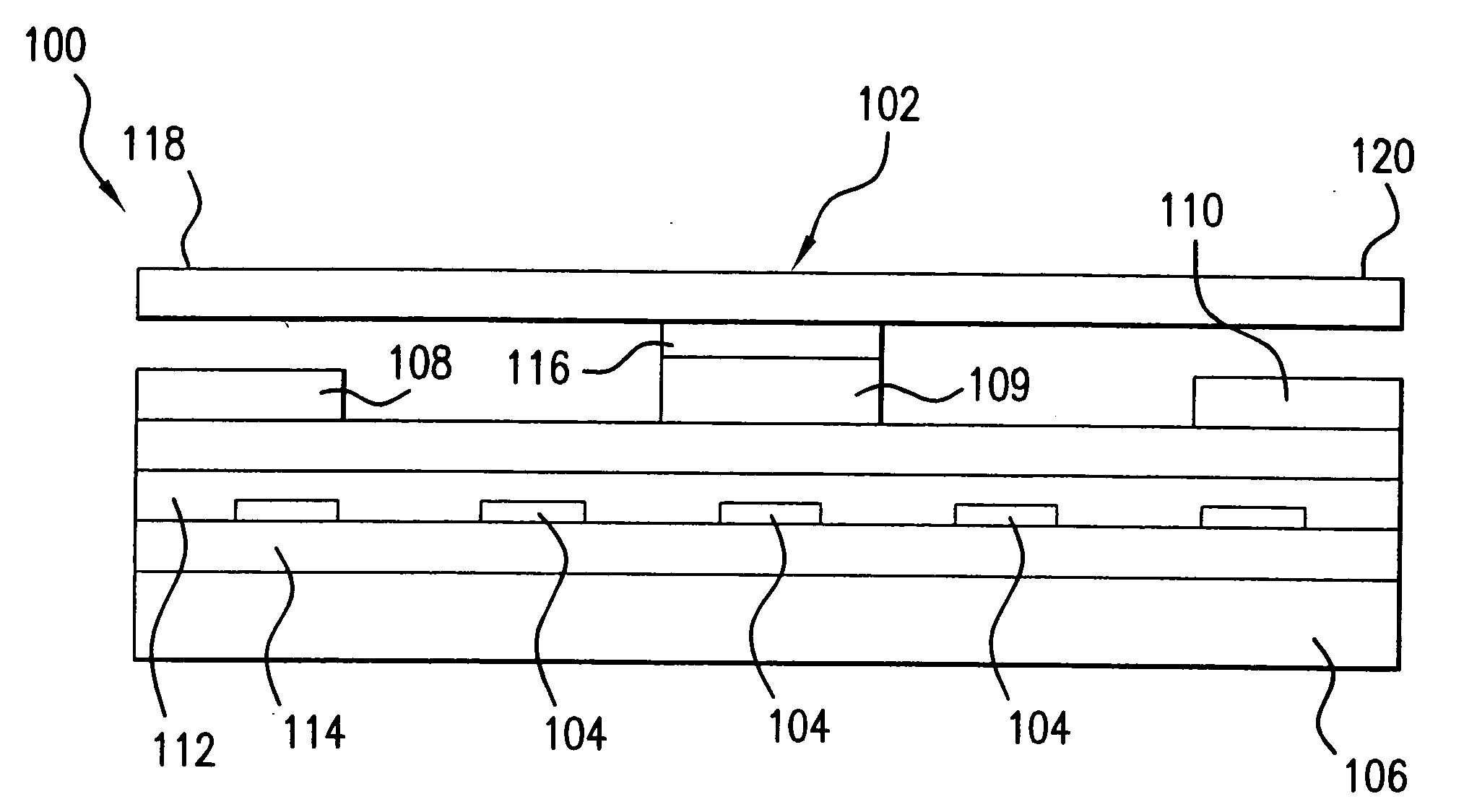
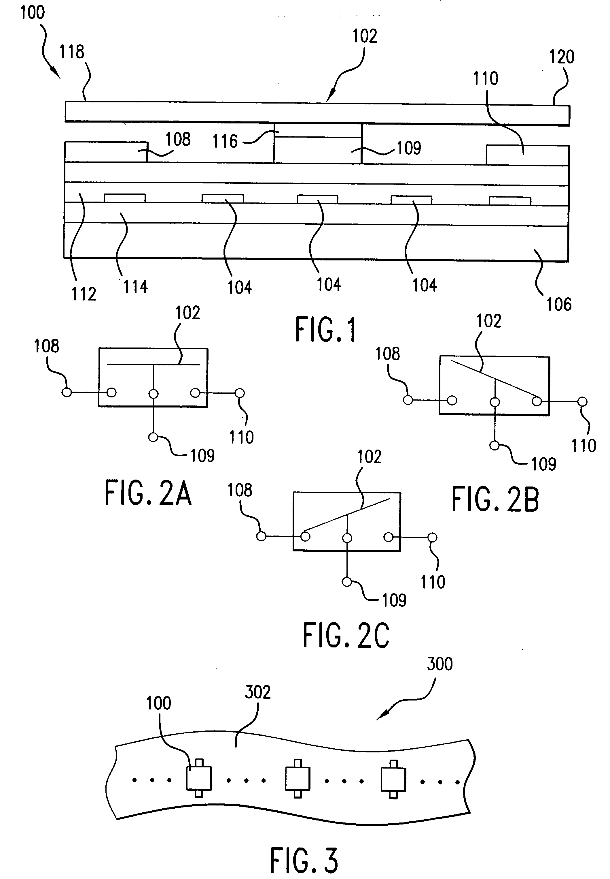
[0053] Embodiments of the present invention provide a micro magnetic proximity sensor including a magnet for producing a magnetic field, a fixed contact, and a cantilever having magnetic material positioned therein to produce a torque on the cantilever in the magnetic field. The magnet can be fixedly mounted adjacent the cantilever, it can be mounted as, or in addition to, the magnetic material positioned in the cantilever, or it can be moveably mounted external to the micro magnetic proximity sensing apparatus. Similar sensors are disclosed in U.S. application Ser. No. 10 / 058,940, entitled “Micro Magnetic Proximity Sensor Apparatus and Sensing Method,” filed Jan. 28, 2002 and U.S. Prov. App. No. 60 / 332,841, entitled “Magnetic Proximity Sensors,” filed Sep. 17, 2001, which are both incorporated herein by reference in their entirety.

[0054] It should be appreciated that the particular implementations shown and described herein are examples of the invention and are not intended to oth...


PUM


Abstract

A system that senses proximity includes a magnet producing a magnetic field and a sensor having a switch. The switch includes a cantilever supported by a supporting structure. The cantilever has a magnetic material and a longitudinal axis. The magnetic material makes the cantilever sensitive to the magnetic field, such that the cantilever is configured to move between first and second states. The switch also includes contacts supported by the support structure. The switch can be configured as a reed switch. When the magnet moves relative to the sensor, the cantilever interacts with a respective one of the contacts based on the position of the magnet during movement. The sensor can have multiple functionalities, such as it can: (1) be used to detect distance to an object, (2) be used to detect direction of a moving object, (3) include a memory that stores a last location of an object; (4) detect ferromagnetic-based materials and hard or soft magnetic objects; (5) be used to detect velocity and/or acceleration of an object and/or (6) be modified to include any function desired by a user.

Description

CROSS-REFERENCE TO RELATED APPLICATIONS [0001] This application is a continuation of U.S. application Ser. No. 10 / 418,076, filed Apr. 18, 2003, which claims the benefit under 35 U.S.C. §119(e) to U.S. Provisional Application No. 60 / 373,605, filed Apr. 19, 2002, which is incorporated by reference herein in its entirety. U.S. application Ser. No. 10 / 418,076 is a continuation-in-part of U.S. application Ser. No. 10 / 058,940 (now U.S. Pat. No. 6,633,158 that issued Oct. 14, 2003), filed on Jan. 28, 2002, which claims priority to U.S. Provisional Application No. 60 / 315,651, filed on Sep. 17, 2001, which are both incorporated herein by reference in their entirety.BACKGROUND OF THE INVENTION [0002] 1. Field of the Invention [0003] The present invention relates to proximity sensors. [0004] 2. Background Art [0005] Switches are typically electrically controlled two-state devices that open and close contacts to effect operation of devices in an electrical or optical circuit. Relays, for exampl...

Claims


Application Information

Patent Timeline
IPC IPC(8): G01B7/14
CPCH01H36/002H01H2036/0093H01H36/0026
Inventor SHEN, JUNRUAN, MEICHUNWEI, CHENGPING
Owner SCHNEIDER ELECTRIC IND SAS
Why Eureka
Try Eureka