Surface acoustic wave apparatus

Inactive Publication Date: 2007-01-11
TAIYO YUDEN KK
View PDF3 Cites 8 Cited by
  • Summary
  • Abstract
  • Description
  • Claims
  • Application Information

AI Technical Summary

Benefits of technology

[0015] It is therefore an object of the present invention to provide a surface acoustic wave apparatus which has a configuration for suppressing the spurious of the higher-order transverse modes and for not changing a SAW excitation intensity distribution in the propagation direction.

Problems solved by technology

This spurious due to the higher-order transverse modes exerts a harmful influence as an oscillating-frequency skip phenomenon in an oscillation circuit in the case of the SAW resonator or an in-band ripple in the SAW resonator filter.
In the case of an IDT electrodes with uniform overlapping length (normal(non-apodized) IDT electrodes), although a desired characteristic, for example, a bandwidth or an attenuation amount in a desired frequency can be achieved, spurious is generated due to the transverse mode.
If the IDT electrodes are weighted by a COS function, although the spurious can be suppressed, a desired characteristic cannot be achieved very frequently.

Method used


Image

  • Surface acoustic wave apparatus
  • Surface acoustic wave apparatus
  • Surface acoustic wave apparatus

Examples


Embodiment Construction

[0033] An embodiment of the present invention will now be described with reference to the drawings. The embodiment is for the purpose of describing the present invention and the technical scope of the present invention is not limited to this.

[0034]FIG. 3 is a diagram showing a configuration of an embodiment of the present invention.

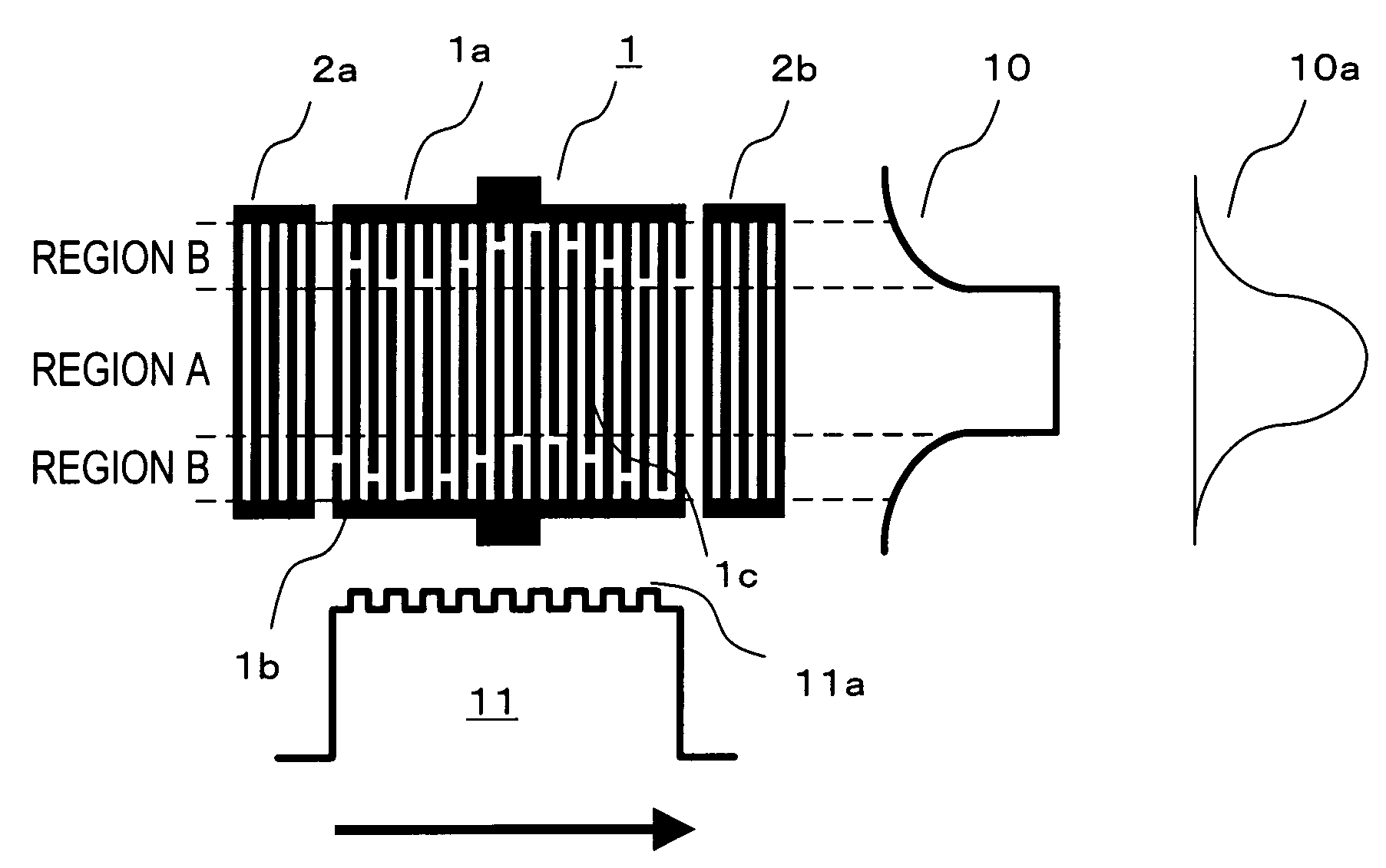
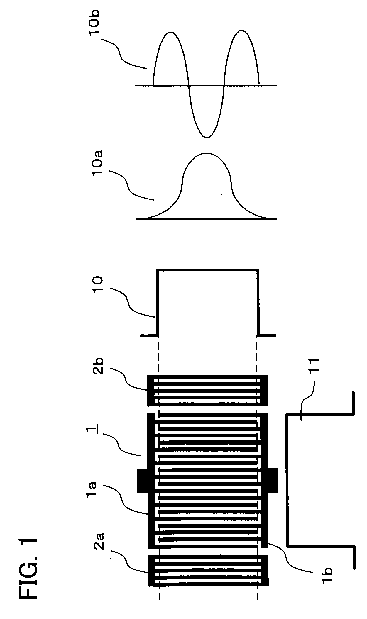
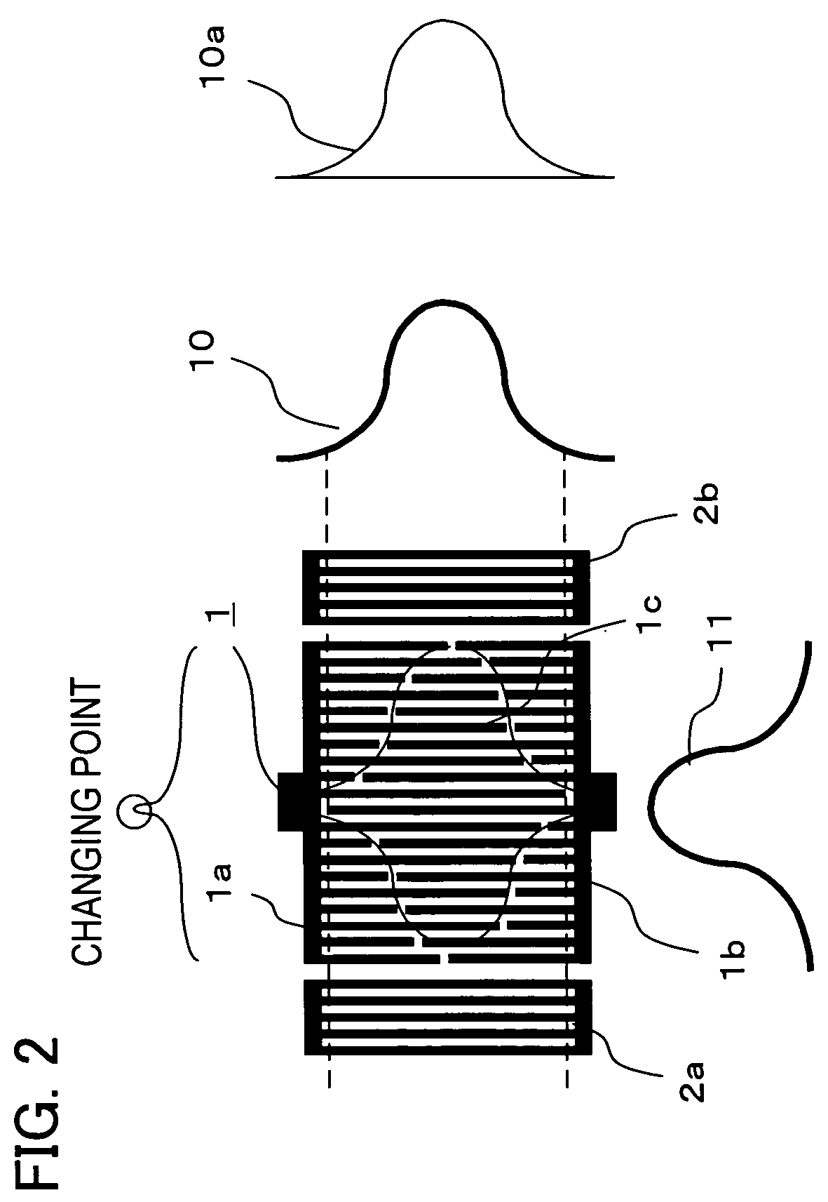
[0035] As shown above in FIG. 1 and FIG. 2, in a surface acoustic wave apparatus with a pair of reflection electrodes 2a, 2b and interdigital transducer 1 disposed between the reflection electrodes 2a, 2b, the reflection electrodes 2a, 2b and the interdigital transducer 1 is formed on a piezoelectric substrate not shown, such as LiTaO3, LiNbO3, Li2B4O7 and quartz.

[0036] As a feature, the interdigital transducer 1 is configured by disposing a plurality of comb-shaped electrodes 1c respectively connected to common electrodes (bus bars) 1a, 1b to be interleaved. For a region where a plurality of comb-shaped electrodes 1c are interleaved, the region has a ...


PUM


Abstract

A surface acoustic wave apparatus has a configuration by which the spurious of the higher-order transverse modes is suppressed and a SAW excitation intensity distribution is not changed in the propagation direction. The surface acoustic wave apparatus has at least one interdigital transducer, which is disposed such that a plurality of comb-shape electrodes respectively connected to common electrodes are interleaved, wherein a region with the plurality of interleaved comb-shape electrodes has a first overlapping region with a overlapping length constant over a whole area along a propagation direction of a surface acoustic wave and a second overlapping region formed on at least one side of the first overlapping region with a overlapping length weighted in the propagation direction of the surface acoustic wave, and wherein an overlapping-length weighting envelope curve in the second overlapping region has at least two changing points in the propagation direction of the surface acoustic wave.

Description

CROSS-REFERENCE TO RELATED APPLICATIONS [0001] This application is based upon and claims the benefit of priority from the prior Japanese Patent Application No. 2005-197364, filed on Jul. 6, 2005, the entire contents of which are incorporated herein by reference. BACKGROUND OF THE INVENTION [0002] 1. Field of the Invention [0003] The present invention relates generally to a surface acoustic wave (SAW) apparatus. More particularly, the present invention relates to a surface acoustic wave filter (SAW resonator filter) configured as a resonator filter using a surface acoustic wave resonator (SAW resonator) or resonator having resonant characteristics in VHF and UHF bands. [0004] 2. Description of the Related Art [0005] Recently, SAW devices are widely used in the telecommunications sector. Especially, SAW resonators or SAW resonator filters (hereinafter, referred to as SAW resonator devices) can be miniaturized and have lower loss and used a lot in mobile phones, remote keyless entry sy...

Claims


Application Information

Patent Timeline
IPC IPC(8): H03H9/64
CPCH03H9/02992H03H9/14532H03H9/1452B42D5/042B42D5/045B42P2241/18B43L1/04
Inventor WADA, KOICHIMITOBE, SEIICHIINOUE, SHOGO
Owner TAIYO YUDEN KK
Why Eureka
Try Eureka