Image capturing device

a technology of image capture and image, which is applied in the direction of instruments, computing, electric digital data processing, etc., can solve the problems of poor filtering out effect and disordered direction of light rays, and achieve the effect of improving the performance of optical mouse, reducing noise, and improving the intensity of light rays

Inactive Publication Date: 2007-01-11
LITE ON TECH CORP
View PDF7 Cites 9 Cited by
  • Summary
  • Abstract
  • Description
  • Claims
  • Application Information

AI Technical Summary

Benefits of technology

[0015] One of the major advantages and improvements is that a placement angle of a light-emitting component is adjusted so that a light ray can be directly guided towards a surface of an object, and then re-directed towards a sensor. In this way, repeated reflection and refraction can be avoided, and the light does not need to pass through many interfaces of different mediums, so the intensity of the light ray will not be weakened. A further advantage is that a light-guiding component is utilized for absorbing an undesired light ray (a noise). Hence, a better quality of an image formation of the sensor can be obtained, and thus the performance of the optical mouse can be improved.

Problems solved by technology

Therefore, the intensity of the light ray decreases each time when the light passes through an interface formed by different mediums, causing the direction of the light ray to become disordered.
By this method, the effect of filtering out the noises is not good.

Method used


Image

  • Image capturing device
  • Image capturing device
  • Image capturing device

Examples


Embodiment Construction

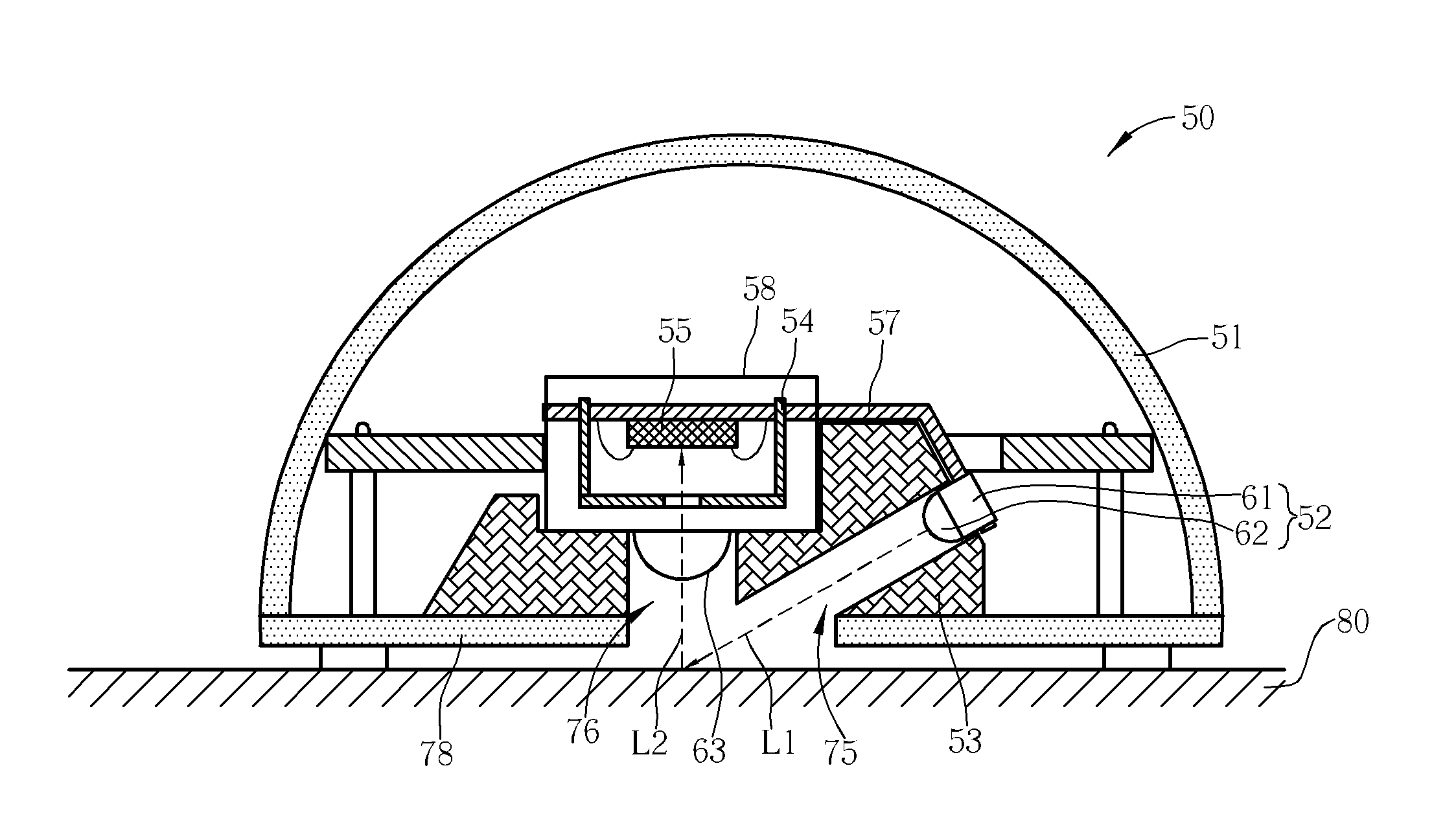
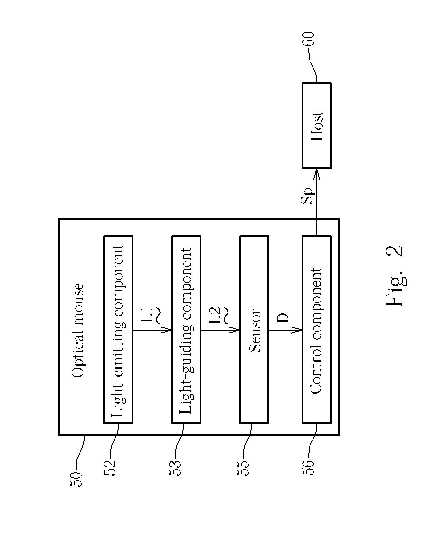
[0021] Please refer to FIG. 2. FIG. 2 is a functional block diagram of an optical mouse 50 according to the present invention. Please note that an optical pointing device (i.e. an optical mouse) is taken as an example to describe the technical characteristics of the present invention; however, the present invention is not limited to be applied to an optical pointing device. The present invention can be applied to any device with an image capturing mechanism, such as a fingerprint recognition device or other types of image recognition devices. As shown in FIG. 2, the optical mouse 50 is coupled to a host 60 (i.e., a computer). In the present embodiment, the optical mouse 50 comprises a light-emitting component 52, a light-guiding component 53, a sensor 55 (i.e., a CCD) and a control component 56. A light-emitting diode (LED) chip 61 in the light-emitting component 52 is utilized for emitting a light ray L1. The light-guiding component 53 defines a straight light-guiding path for guid...


PUM


Abstract

An image capturing device is disclosed. The image capturing device includes: a light-emitting component for generating a light ray; a light-guiding component for providing a first straight light-guiding path to guide the light ray generated by the light-emitting component toward a surface; and a sensor for sensing the light ray reflected by the surface to detect a movement of the image capturing device on the surface.

Description

BACKGROUND OF THE INVENTION [0001] 1. Field of the Invention [0002] The present invention relates to an image capturing device, and more specifically, to an image capturing device capable of providing straight light-guiding paths and comprising a light-guiding component that is composed of opaque material(s). [0003] 2. Description of the Prior Art [0004] Image capturing technologies are popularly applied to several kinds of electronic devices, such as an optical mouse, or a fingerprint recognition device. An optical mouse according to a prior art is herein taken as an example. The operation of the optical mouse is described as follows. In general, a light-emitting component of the optical mouse emits a light ray that will arrive at a surface of an object (i.e., a surface of a desk or a mouse pad). Next, a sensor of the optical mouse senses the light ray reflected by the surface to generate a corresponding image. In this way, when the optical mouse moves on the surface, the optical m...

Claims


Application Information

Patent Timeline
Patent Type & Authority Applications(United States)
IPC IPC(8): G09G5/08
CPCG06F3/03543G06F3/0317
Inventor CHIU, HO-FENGKUO, CHENG-CHUNGWENG, JEN-CHUN
Owner LITE ON TECH CORP
Why Eureka
Try Eureka