Ink-jet recording device and ink-jet recording control method

a recording device and inkjet technology, applied in the direction of printing mechanism, spacing mechanism, printing, etc., can solve the problems of poor usability, deterioration of image factor, leaning, etc., and achieve the effect of preventing image deterioration

Inactive Publication Date: 2007-01-11
CANON KK
View PDF1 Cites 13 Cited by
  • Summary
  • Abstract
  • Description
  • Claims
  • Application Information

AI Technical Summary

Benefits of technology

[0042] An embodiment of the present invention is provided to address the above problems, and provide a recording device for preventing an image from deterioration due to the recording positional deviation of a reco...

Problems solved by technology

Also, the mounting accuracy of the recording head and manufacturing irregularities cause a leaning (slanting) as to the mains-scanning direction of the discharge orifice rows.
Consequently, manufacturing irregularities of recording heads, and the accuracy at the time of mounting a recording head on the recording device become important factors.
As described above, with the recording head having no leaning θ such as FIG. 2, the ...

Method used


Image

  • Ink-jet recording device and ink-jet recording control method
  • Ink-jet recording device and ink-jet recording control method
  • Ink-jet recording device and ink-jet recording control method

Examples


first exemplary embodiment

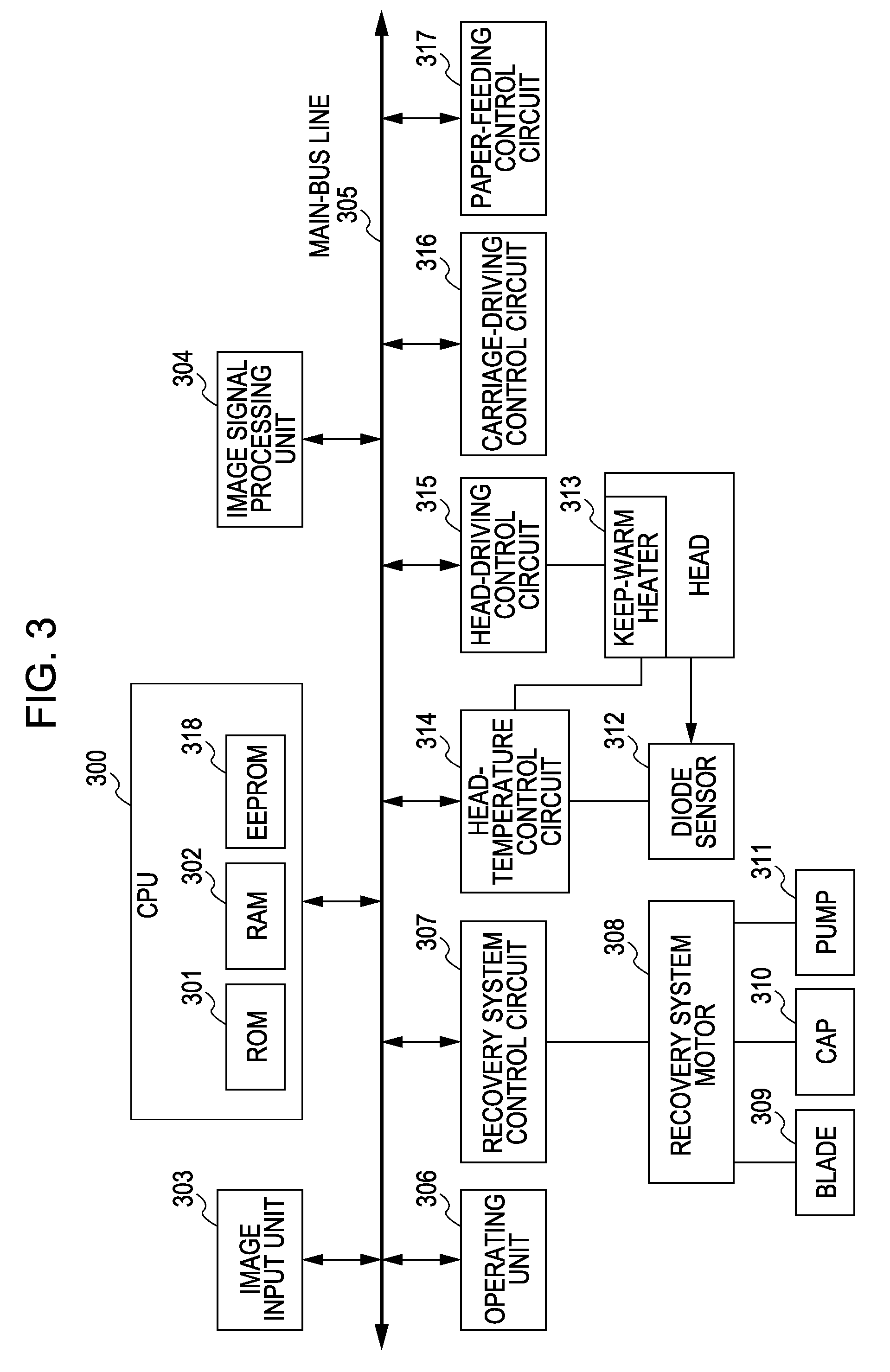
[0090]FIG. 3 is a block diagram illustrating a control configuration of an ink-jet recording device according to an embodiment of the present invention. Let us say that the mechanical configuration of the ink-jet recording device according to the present embodiment is the same as that illustrated in FIG. 1. The control configuration is classified broadly into a processing section for controlling printing data and firmware, such as an image input unit 303, an image signal processing unit 304 corresponding thereto, and a central processing unit CPU 300, and hardware system processing section, such as an operating unit 306, a recovery system control circuit 307, a head-temperature control circuit 314, a head-driving control circuit 315, a carriage-driving control circuit 316 toward the main-scanning direction, and a sheet feeding control circuit 317 toward the sub-scanning direction, which access to a main-bus line 305 respectively. The CPU 300 generally includes ROM (Read Only Memory)...

second exemplary embodiment

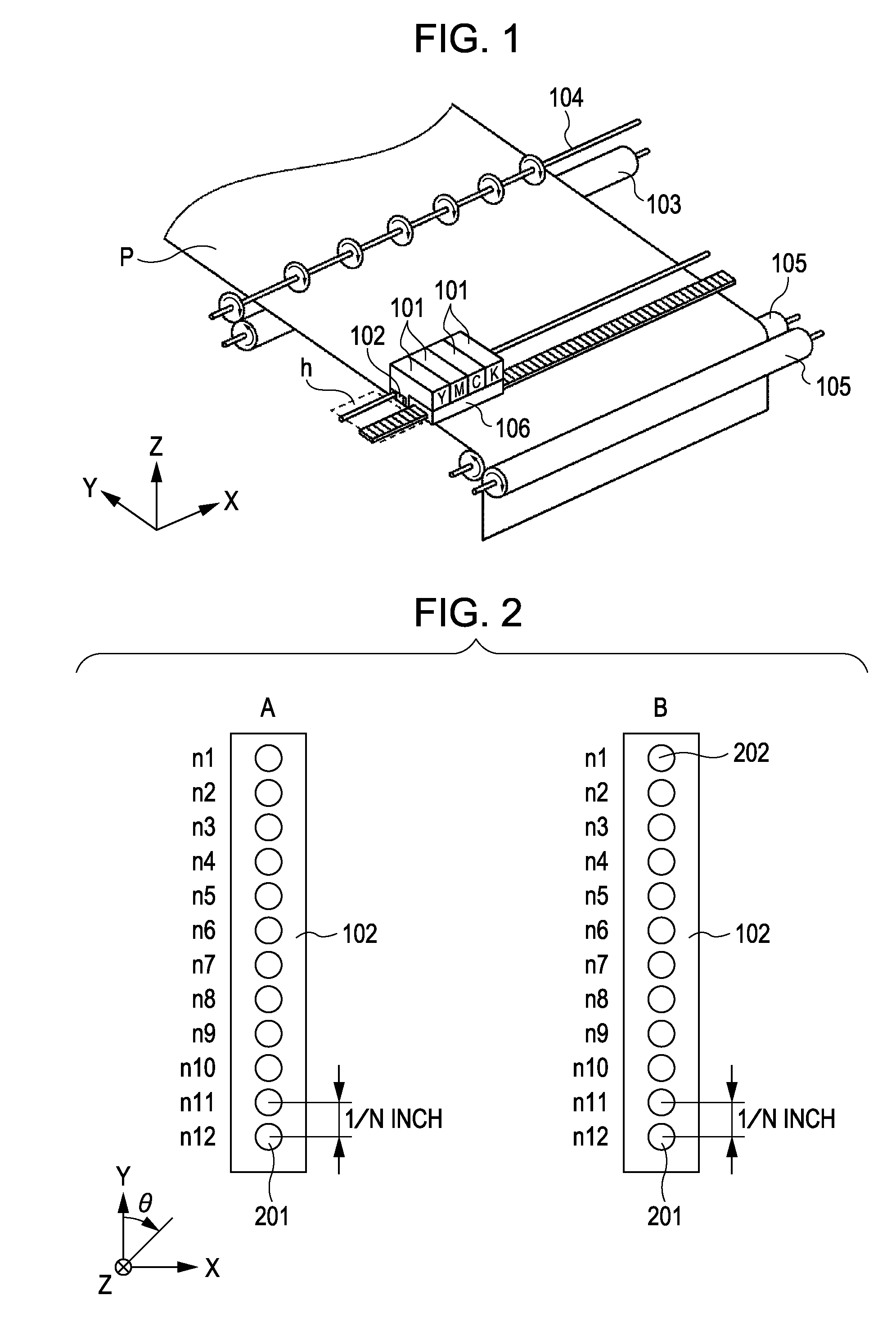
[0105] With the second embodiment of the present invention, description will be made regarding a case in which two recording heads each made up of the two ink discharge orifice rows illustrated in FIG. 16. FIG. 16 illustrates the two recording heads of a recording head 2601 including the two rows of the ink discharge orifice row A for discharging black ink, and the ink discharge orifice row B for discharging cyan ink, and a recording head 2602 including the two rows of the ink discharge orifice row C for discharging magenta ink, and the ink discharge orifice row D for discharging yellow ink.

[0106] The recording heads are each configured so as to have the number of ink discharge orifices L=12, and recording pixel density of 600 dpi based on the interval of the ink discharge orifices of 1 / 600 inch. Also, the amount of discharge from the recording head is arranged such that approximately 2-pl ink droplet per one droplet can be discharged, and the discharge frequency for discharging th...

third embodiment

[0133] With the present embodiment, description will be made regarding a case in which of ink discharge orifices to be employed for adjusting the driving timing between two types of ink discharge orifice rows, at least one type of ink discharge orifice row includes an ink discharge orifice serving as the reference of ink discharge orifice rows.

[0134]FIG. 36 illustrates recording heads for describing the present embodiment.

[0135] The recording heads are made up of a recording head A having a discharge orifice interval of 1 / 600 inch, and 18 discharge orifices, and a recording head B having a discharge orifice interval of 1 / 600 inch, and 12 discharge orifices.

[0136] Let us say that the ink discharge orifice groups of the recording head A, which are employed for adjustment of a recording positional deviation in the rotational direction θ within an ink discharge orifice row, are three groups of n1 through n6, n7 through n12, and n13 through n18, and an ink discharge orifice group serv...


PUM


Abstract

An ink-jet recording device is capable of correcting a recording position due to a leaning of a printing head and correcting of driving timing between multiple printing heads. Each nozzle row of a printing head is classified into multiple nozzle groups, and the driving timing of the nozzle groups other than the nozzle group serving as a reference of correction of the multiple nozzle groups is adjustable to correct for any leaning of the printing head. Moreover, in the event of performing the driving timing between printing heads, the driving timing of a non-reference printing head is adjustable relative to a reference printing head employed for leaning correction of multiple printing heads.

Description

BACKGROUND OF THE INVENTION [0001] 1. Field of the Invention [0002] The present invention relates to an ink-jet recording device and a recording control method thereof, and particularly relates to a configuration and method for adjusting the deviation of a recording position. [0003] 2. Description of the Related Art [0004] A common ink-jet recording device includes a recording head including multiple recording elements which are integrated and arrayed for improving recording speed, an ink discharge unit in which multiple ink discharge orifices and liquid paths are integrated, and further the multiple recording heads corresponding to multiple colors. [0005]FIG. 1 illustrates a configuration of an ink-jet printer unit at the time of recording on a surface of a recording sheet using the above-described recording head. In the drawing, reference numeral 101 denotes ink cartridges. The ink cartridges comprise ink tanks in which ink of four colors of black, cyan, magenta, and yellow is fil...

Claims


Application Information

Patent Timeline
IPC IPC(8): B41J29/38
CPCB41J29/393B41J2/07B41J2029/3935B41J2/2135B41J19/145
Inventor HAYASHI, AYAMORIYAMA, JIROKANDA, HIDEHIKOHAMASAKI, YUJIKAWATOKO, NORIHIROCHIKUMA, TOSHIYUKISAKAMOTO, ATSUSHITANAKA, HIROKAZUHAYASHI, MASASHI
Owner CANON KK
Why Eureka
Try Eureka