Liquid ejecting apparatus

Inactive Publication Date: 2007-01-11
SEIKO EPSON CORP
View PDF3 Cites 15 Cited by
  • Summary
  • Abstract
  • Description
  • Claims
  • Application Information

AI Technical Summary

Benefits of technology

[0021] It is therefore an object of the invention to provide a liquid ejecting apparatus which enables a high

Problems solved by technology

When each part is thus increased in size, it becomes difficult to maintain a high processing accuracy, and processing equipment has to be subjected to an overhaul in order to carry out a processing with high accuracy.
Moreover, when intending to fabricate large-size parts with high accuracy, a significant reduction e

Method used


Image

  • Liquid ejecting apparatus
  • Liquid ejecting apparatus
  • Liquid ejecting apparatus

Examples


Example

[0039] Next, an embodiment of the invention will be described in detail.

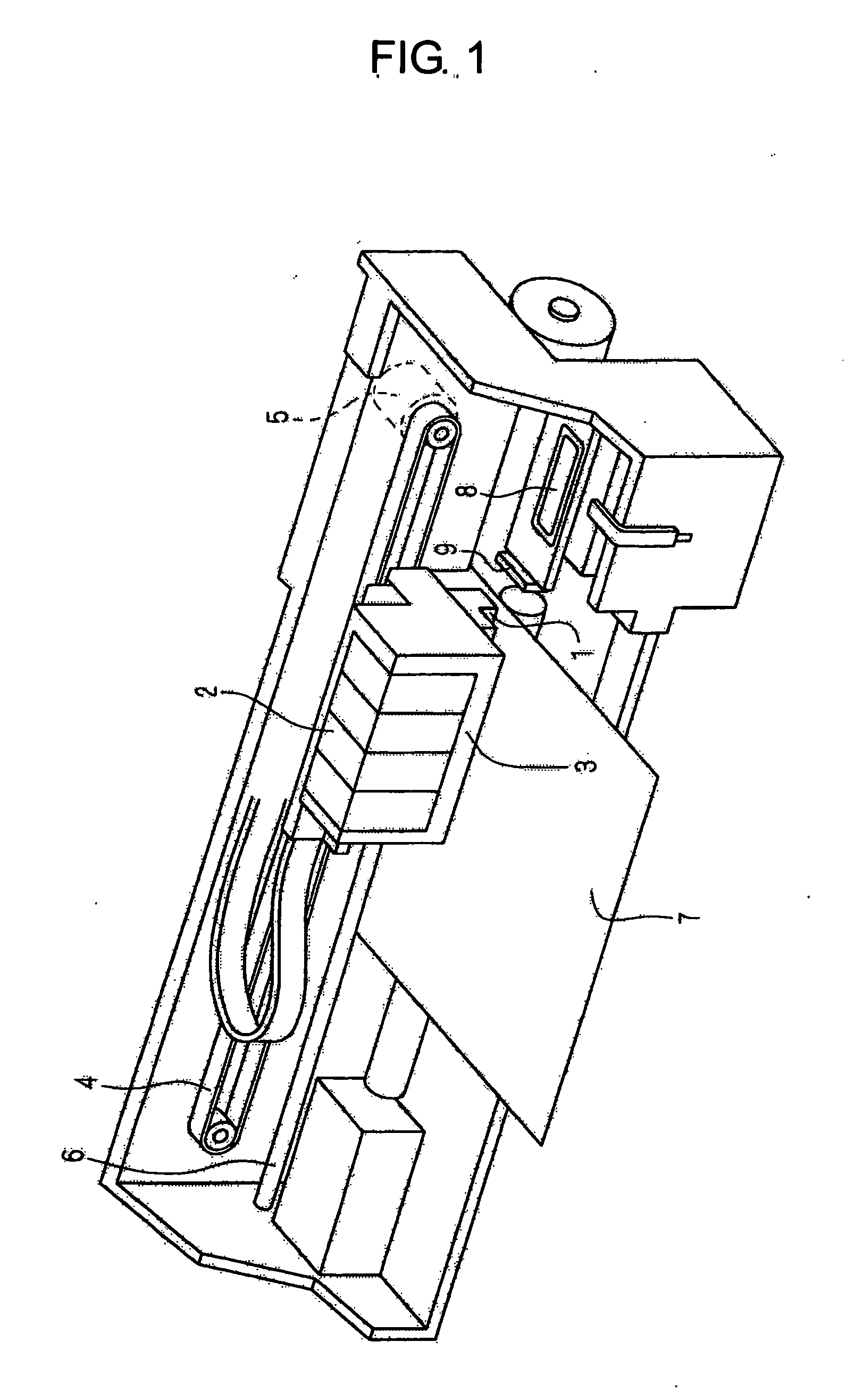
[0040]FIG. 1 is a view showing an example of a peripheral structure of an inkjet recording apparatus applying the liquid ejecting apparatus of the invention.

[0041] The recording apparatus includes a carriage 3 on the top of which an ink cartridge 2 serving as a liquid supply source is mounted and to the underside of which an ejecting head 1 ejecting ink droplets is attached.

[0042] The carriage 3, being connected to a stepping motor 5 via a timing belt 4, is configured in such a way as to, while being guided by a guide bar 6, reciprocate in a paper width direction of a recording paper 7. Also, the ejecting head 1 is attached to a surface (in this example, the underside) of the carriage 3 facing the recording paper 7. A configuration is such that the ejecting head 1 is supplied with ink from the ink cartridge 2 and, while the carriage 3 is being moved, ejects ink droplets onto an upper surface of the recording ...


PUM


Abstract

A liquid ejecting apparatus includes: a plurality of flow channel units, each of which includes a pressure generating chamber operable to generate pressure therein and a nozzle plate formed with a nozzle from which liquid is ejected by the pressure; a plurality of drive units, each of which includes a piezoelectric vibrator operable to apply a pressure vibration to the pressure generating chamber, and which correspond to the plurality of the flow channel units, respectively; and a head casing, in which the plurality of the drive units are stored, and to which the plurality of the flow channel units are fixed.

Description

BACKGROUND OF THE INVENTION [0001] The present invention relates to a liquid ejecting apparatus which ejects a liquid, supplied from a liquid cartridge and the like, in the form of liquid droplets, and particularly to a liquid ejecting apparatus which enables a high speed printing by realizing a reduction in its size while increasing the number of nozzles of an ejecting head. [0002] As one kind of liquid ejecting apparatus, there is an inkjet recording apparatus. Such an inkjet recording apparatus has advantages of, as well as being able to print directly on a recording medium, being easy to reduce the size of a head, and furthermore that a color printing can also be easily carried out by changing ink colors. [0003]FIG. 8 is one representative example of an ejecting head used for the recording apparatus described heretofore. The ejecting head includes a head casing 76, in which a piezoelectric vibrator 74 serving as pressure generating means is stored, and a flow channel unit 86, wh...

Claims


Application Information

Patent Timeline
IPC IPC(8): B41J2/05
CPCB41J2/14274B41J2/15B41J2202/20B41J2/14233B41J2/16505B41J2002/14459B41J2/045B41J2/14B41J2/1433B41J2/161B41J2/14201B41J2002/14491B41J2/14209
Inventor AKAHANE, FUJIO
Owner SEIKO EPSON CORP
Why Eureka
Try Eureka