Apparatus and methods for securing discharge chutes on mixing vehicles

Inactive Publication Date: 2007-01-11
JOHNSON BRIAN KEITH
View PDF12 Cites 12 Cited by
  • Summary
  • Abstract
  • Description
  • Claims
  • Application Information

AI Technical Summary

Benefits of technology

[0007] Some prior devices for securing the position of a chute include manual operable clamp assemblies mounted to a pivoted chute brace. These clamp assemblies typically consist of a threaded shaft at one end of an upright brace bearing shaft. A wheel is typically threadably engag

Problems solved by technology

When disposed along a long extension, the dynamic mass of concrete can produce significant torque at the connection of the discharge chute to the vehicle.
Given the pivoting nature of a typical discharge chute, the forces on the discharge chute can produce movement which is difficult to manually control and may result in unwanted movement of the discharge chute.
This movement of the discharge chute can result in the misdirection of the liquid concrete which wastes both the concrete and the man-hours needed for cleanup.
In addition, a freely swinging chute can present a significant safety hazard for those working around the discharge chute.
The hydraulic cylinder requires use of an expensive and complex hydraulic system that is not typically supplied as standard equipment on concrete mixing trucks.
Hydraulic cylinders wear quickly when exposed to concrete with its naturally abrasive component.
Furthermore, use of a hydraulic cylinder could be considered “overkill”, since the primary need is not for powered movement of the chute.
The Potter device and other known “detent” type chute locking mechanisms do allow positive positioning of the discharge chute at the pivot point between the discharge chute and stationary frame but do not enable infinite angular adjustment for precise pouring.
Further, such mechanisms will not effectively operate to stop a moving discharge chute without causing possible damage to the lockout mechanism.
Difficulty is also experienced in removing and placing the lock pin when the discharge chute is loaded.

Method used


Image

  • Apparatus and methods for securing discharge chutes on mixing vehicles
  • Apparatus and methods for securing discharge chutes on mixing vehicles
  • Apparatus and methods for securing discharge chutes on mixing vehicles

Examples


Embodiment Construction

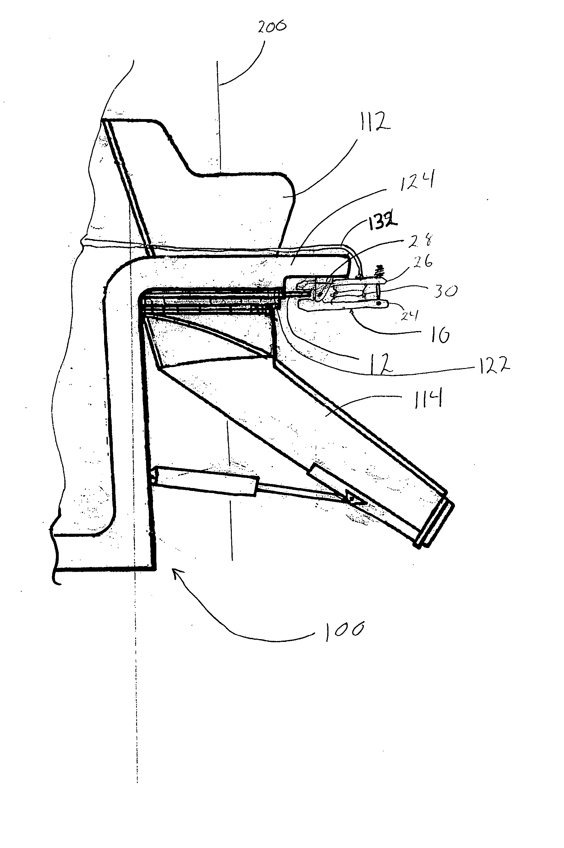
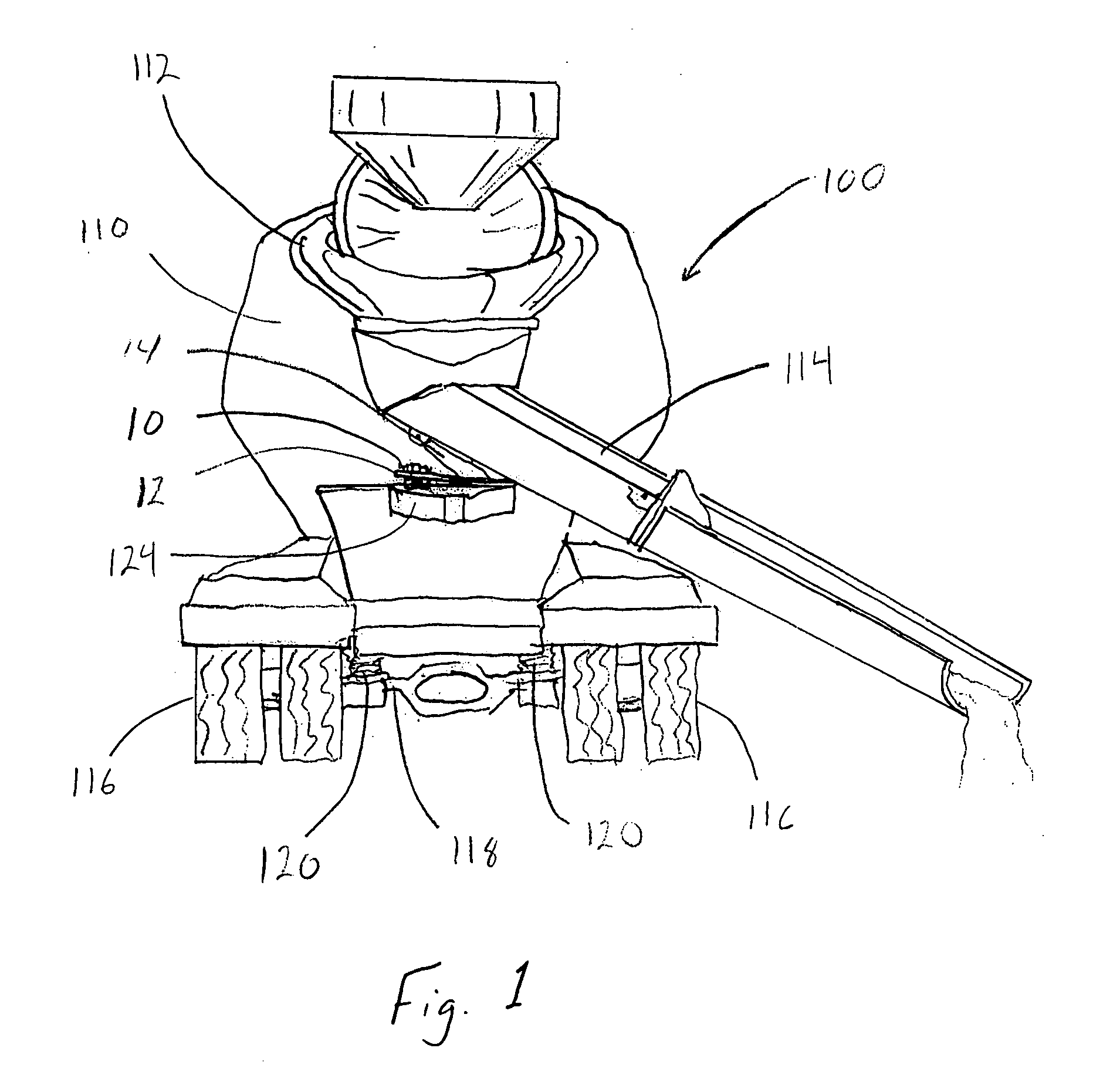
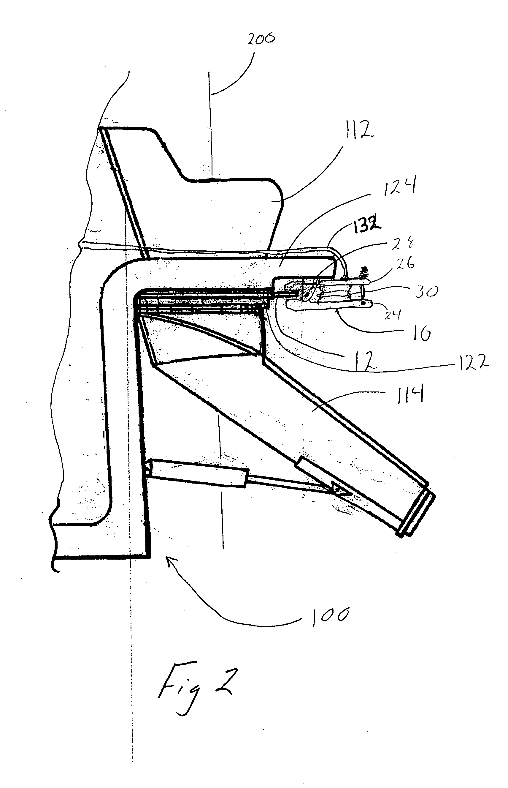
[0028] The present invention is intended for use on mixing vehicles 100. These vehicles 100 are frequently configured and utilized for mixing concrete. For exemplary purposes and ease of description, the following description describes the invention in association with a concrete mixing truck as the vehicle 100. Vehicles 100 typically include a mixing drum 110 rotatably mounted to the vehicle 100. The drum 110 includes a discharge opening. The discharge opening typically faces frontward or rearward with respect to the front and rear of the vehicle 100. A hopper 112 is typically positioned adjacent to the discharge opening. A discharge chute 114 is typically positioned below the hopper 112 for receiving the concrete discharged from the discharge opening. The discharge chute 114 is typically mounted to the vehicle 100 to pivot about a vertical axis. The discharge chute 114 is also typically extendable to one or more elongated positions. Accordingly, the discharge chute 114 may direct ...


PUM


Abstract

Apparatus and methods for locking a discharge chute of a mixing vehicle are disclosed. The locking apparatus can be mounted to existing discharge chutes and frame arrangements and may utilize existing pneumatic systems of the mixing vehicle. The locking apparatus generally include a base having a first arm and a second arm pivotally secured to the base. An airbag may be positioned between the first arm and the second arm to bias a clamping region of the locking apparatus in a locked or a released state depending on the configuration of the locking apparatus.

Description

BACKGROUND OF THE INVENTION [0001] 1. Summary of the Invention [0002] The present invention relates to discharge chutes on mixing vehicles and, more particularly, to apparatus and methods securing a discharge chute at a desired position about its range of motion. [0003] 2. Description of the Related Art [0004] Vehicles designed to mix and transport concrete typically include mixing drums in which the liquid concrete is held during transportation. The mixing drums normally have a capacity of between seven and ten cubic yards of concrete. This volume of concrete typically weighs between 28,000 lbs and 40,000 lbs. The mixing drums typically rotate on the mixing vehicle to agitate the mass of liquid concrete and to prevent it from setting during transport. [0005] The mixing drums are typically set at an angle on the mixing vehicle which places the discharge opening of the mixing drum above the level of a full load of concrete. When the concrete is to be discharged, rotation of the drum ...

Claims


Application Information

Patent Timeline
IPC IPC(8): B28C7/16
CPCB65G11/18B28C5/4248
Inventor JOHNSON, BRIAN KEITH
Owner JOHNSON BRIAN KEITH
Why Eureka
Try Eureka