Image transmitting apparatus and image receiving apparatus

a technology of image transmitting apparatus and receiving apparatus, which is applied in the direction of instruments, computing, code conversion, etc., can solve the problems of intolerant circuit cost, critical limit of improvement of circuit, and emi problem

Inactive Publication Date: 2007-01-11
KK TOSHIBA
View PDF4 Cites 25 Cited by
  • Summary
  • Abstract
  • Description
  • Claims
  • Application Information

AI Technical Summary

Problems solved by technology

This massive data transfer in recent years inevitably causes an EMI problem.
This rapid increase implies that the circuit is requested to operate at higher frequency, and the cost of circuit is becoming more intolerant.
Therefore, the improvements of circuit will reach critical limit in the near future.
Power consumption is an important factor in electronic devices especially in the case that the device is power-supplied by batteries in cellular phone.
In addition, higher speed operation of circuit is not desirable.
An extra control circuit is not desirable in order to implement the adjustment.
Since this official gazette also treats “general data”, not specialized for image data, image data cannot be processed effectively from the aspect of utilization of statistical characteristic of image.
Hence, it is impossible to obtain so large enough effect that EMI noise is fully reduced.
In the techniques, “1H” prediction, “1V” prediction, and a spatial predictor are so simple that its resultant performance is insufficient.
Hence, its performance is not good for natural images such as a TV screen image.
But, prioritizing of area-efficient implementation may select another choice if necessary, because the other predictor with rather inferior performance may have smaller hardware.
Therefore, both purposes cannot be solved simultaneously and single purpose needs to be selected.
In the case of lossless, code allocation has no flexibility to mitigate multiple purposes simultaneously because lossless requires many code words in order to realize lossless.
The multiple purposes will not be fulfilled simultaneously until lossy or near-lossless technologies are permitted.

Method used


Image

  • Image transmitting apparatus and image receiving apparatus
  • Image transmitting apparatus and image receiving apparatus
  • Image transmitting apparatus and image receiving apparatus

Examples


second embodiment

[0140] The second embodiment will furthermore reduce level of multi-valuation for code word than the first embodiment.

[0141]FIG. 13 is an instance of code table. In FIG. 13, the box with bold border marks the code words with average amplitude 0.75. The embodiment will try to remove the code word whose average amplitude is 0.75. In FIG. 13, code words with average amplitude 0.75 are twelve in total count. It includes two 4-valued code words (with coded by using a digit “3”). When average amplitude is same for two code words, a desirable choice is a code word consisting with smaller digits, in order to reduce level of multi-valuation. Therefore, in the embodiment, the 4-valued code words are to be removed. For this removal, although the code word has still larger average amplitude but very less occurrence frequency, thus such partial removal gives no significant affect for image quality as a result.

[0142]FIG. 14 is a modified code table of FIG. 13, where 4-valued code word has been ...

third embodiment

[0153] The third embodiment will treat both transition count and average amplitude when sorting code words in a code table.

[0154] As the embodiment will serially transfer code word Δ3Δ2Δ1Δ0, here, its order becomes meaningful. FIG. 17 is a timing diagram of the data transfer within four cycles. In the case of FIG. 17, image data for two pixels is transferred within four cycles. As shown, image data for R-G, G, and B-G are serially transmitted within four cycles in the similar format, respectively.

[0155] In the case adopting a transfer such as shown in FIG. 17, smaller transition count is preferable for the improvement: the smaller transition count of data becomes, the less power consumption becomes, and the less EMI noise.

[0156]FIG. 18 is a modified code table of FIG. 8 where a new column is added to show transition counts of code word. In FIG. 18, sort the code words with average amplitude in the first priority, and simultaneously sort them with transition count in the second pr...

fourth embodiment

[0159] The fourth embodiment will illustrate a coding by considering only transition count without average amplitude.

[0160]FIG. 19 is an encoding table to minimize the transition count. The column “Code 1” gives code words when the last transferred code word ended in 0, and the column “Code 2” gives code words when the last transferred code word ended in 1. In the both cases, code words are sorted in the ascending order by transition count (with smaller count first).

[0161] The code table in FIG. 19 does not include all possible code word. FIG. 20 shows a list of code words not used in the code table in FIG. 19.

[0162]FIG. 21 shows analyzed results with adding “qQuiet” of FIG. 19 to FIG. 16. For “qQuiet”, the abscissa axis denotes transition count. By comparing with FIG. 16, the curve “cb3” of “qQuiet” is slightly shifted to the left from the curve “cb1” of “qOAC3h”. The values are almost similar: average amplitude is roughly 1 / 17 for MPEG, roughly 1 / 13 for JPEG and roughly ⅕ for T...


PUM


Abstract

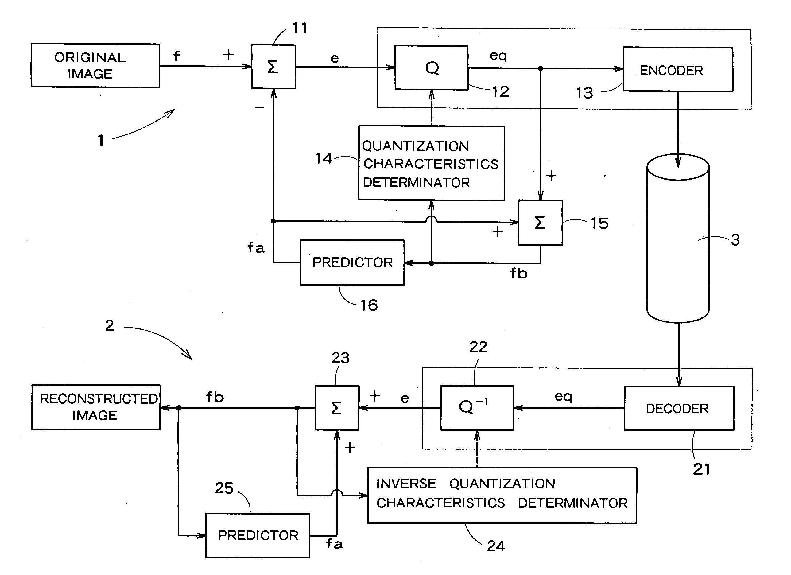
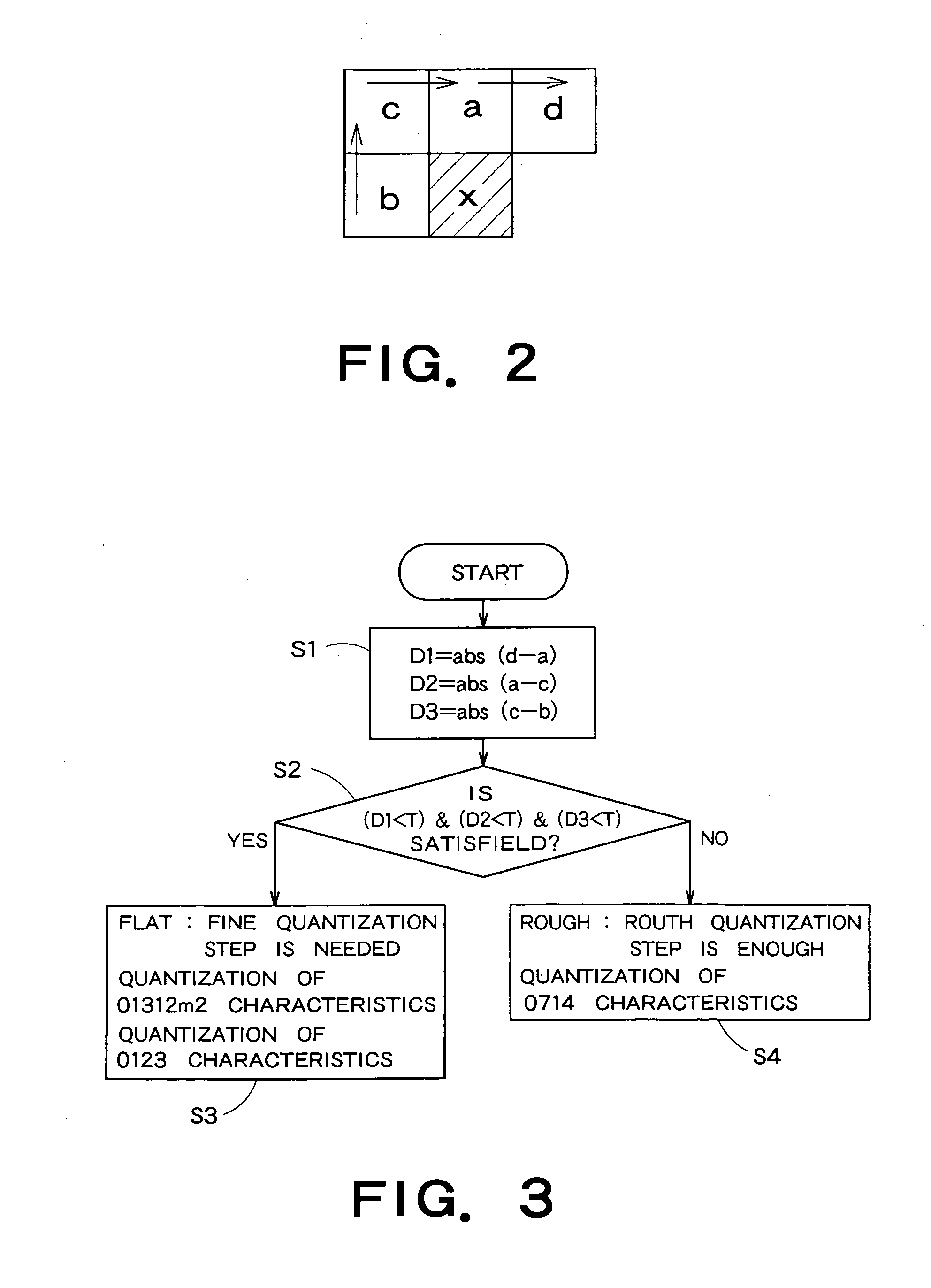
An image transmission apparatus has a difference calculator configured to calculate a difference between actual image data and current predicted data based on previous data, a quantizer configured to generate quantized difference data obtained by quantizing the difference, a quantization characteristic determinator configured to determine a quantization characteristic corresponding to the quantizer based on pixel values of a plurality of neighbor pixels located in surroundings of a current pixel, and a encoder configured to generate code word to be transmitted via a least single transmission line based on the quantized difference data.

Description

CROSS REFERENCE TO RELATED APPLICATIONS [0001] This application is based upon and claims the benefit of priority from the prior Japanese Patent Application No. 2005-201287, filed on Jul. 11, 2005, the entire contents of which are incorporated herein by reference. BACKGROUND OF THE INVENTION [0002] 1. Field of the Invention [0003] The present invention relates to an image transmitting apparatus and an image receiving apparatus for transmitting or receiving image data. [0004] 2. Related Art [0005] In order to deal with high resolution and high quality image data, it is necessary to transmit massive image data. This massive data transfer in recent years inevitably causes an EMI problem. [0006] The number of pixels in pixel data dealt by electronic appliances has been increasing year by year. The number is estimated to increase at a rate of 1.6 times per three years based on its tendency up to date. The number of pixels and a transmission frequency of data are almost in proportion to ea...

Claims


Application Information

Patent Timeline
Patent Type & Authority Applications(United States)
IPC IPC(8): G06K9/36G09G3/20G09G3/36H03M7/36H04N1/417H04N19/124H04N19/134H04N19/136H04N19/137H04N19/182H04N19/186H04N19/196H04N19/50H04N19/503H04N19/91
CPCH04N19/61H04N19/14H04N19/126
Inventor SASAKI, HISASHIOKUMURA, HARUHIKO
Owner KK TOSHIBA
Why Eureka
Try Eureka