
Reconfigurable memory module and method

a memory module and reconfigurable technology, applied in the field of memory systems, can solve the problems of inability to provide optimal performance in memory systems and inability to easily alter data formats

Inactive Publication Date: 2007-01-11
ROUND ROCK RES LLC
View PDF99 Cites 55 Cited by
  • Summary
  • Abstract
  • Description
  • Claims
  • Application Information

AI Technical Summary

Benefits of technology

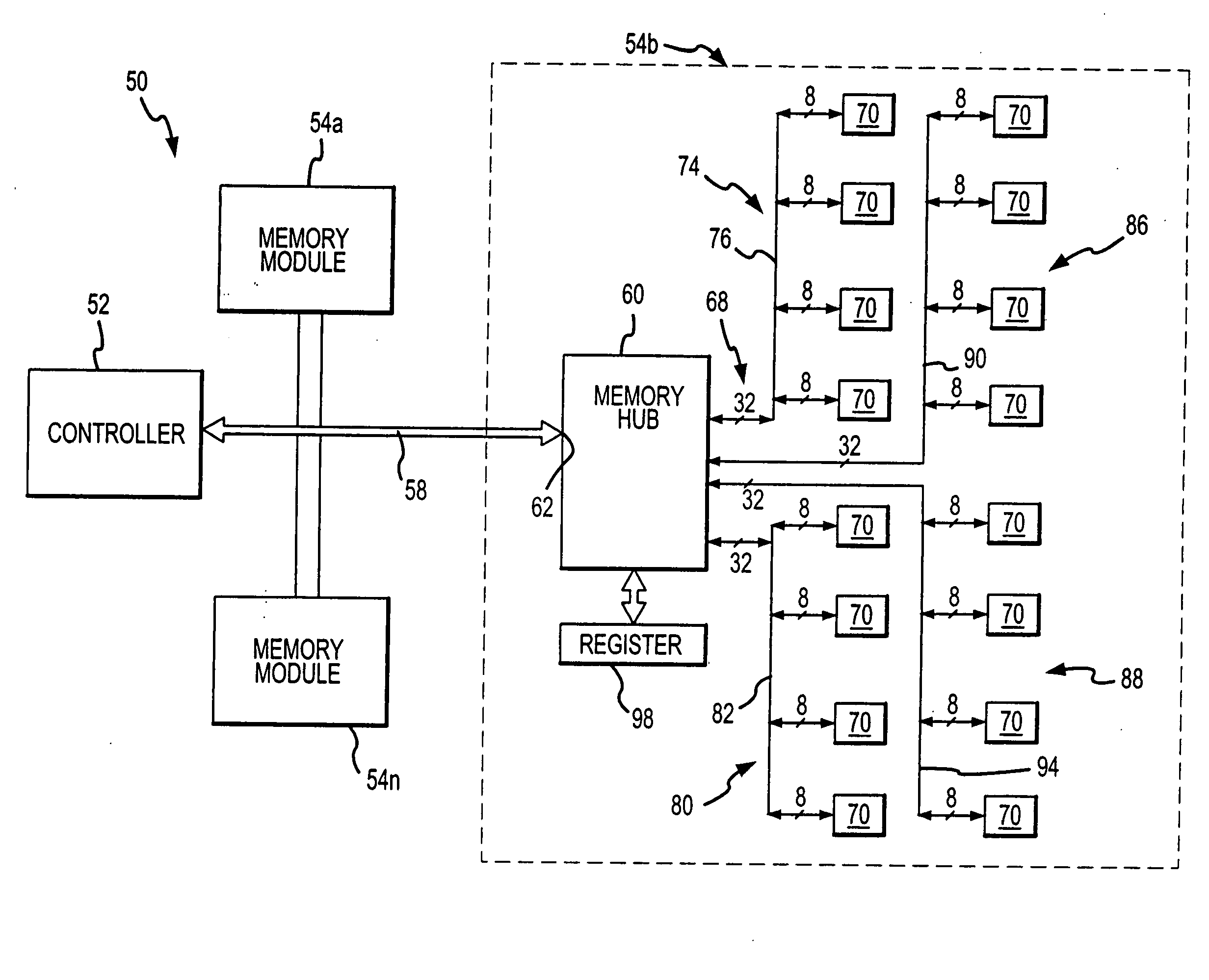
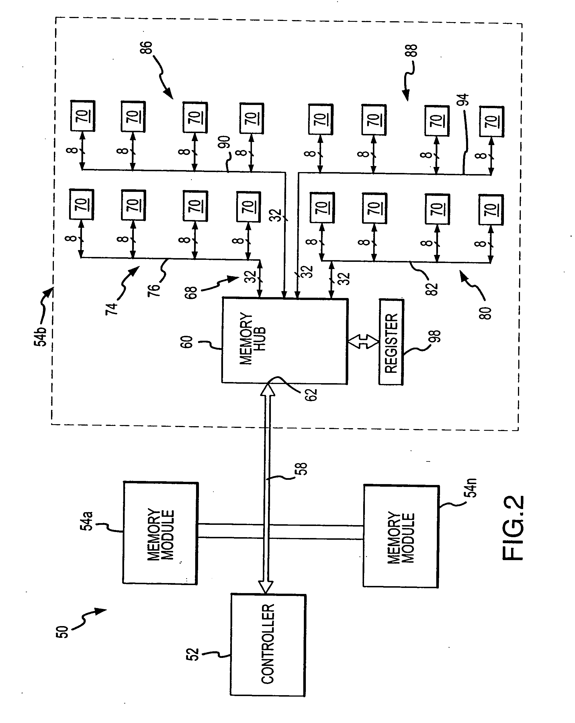
"The patent describes a memory system that can be used in a computer system. The system includes a controller and multiple memory modules. Each module has a memory hub that can be programmed to access memory devices in different formats simultaneously. The memory hub can be programmed for high bandwidth or high memory depth. The technical effect of this system is that it allows for efficient memory access and flexibility in data format and bandwidth requirements."

Problems solved by technology

Unfortunately, the memory system must be optimized for either high memory bandwidth, high memory depth or a combination of bandwidth and depth.
Insofar as the data format selected is determined by the hardware design, is not possible to easily alter the data format.
In such cases, the memory system cannot provide optimum performance.

Method used


Image

  • Reconfigurable memory module and method
  • Reconfigurable memory module and method
  • Reconfigurable memory module and method

Examples


Embodiment Construction

[0015] A memory system 50 according to one example of the invention is shown in FIG. 2. The memory system 50 includes a controller 52 coupled to several memory modules 54a, b . . . n through a high-speed link 58. The controller 52 may be coupled to a memory access device, such as a processor (not shown), or it may be, for example, itself a processor. The high-speed link 58 may be a bus formed by multiple conductors, an optical communication link, and RF communication link, or some other type of high-speed communication link. Typically, the high-speed link 58 will have a capacity for coupling data having a predetermined bus width between the controller 52 and each memory module 54. In the example shown in FIG. 2, the link 58 couples a 32-bit data word. The high-speed link 58 also couples address and command signals from the controller 52 to the memory modules 54. Although the high-speed link 58 is shown in FIG. 2 as having a multi-drop topology in which the link 58 is coupled to seve...


PUM


Abstract

A computer system includes a controller coupled to a plurality of memory modules each of which includes a memory hub and a plurality of memory devices divided into a plurality of ranks. The memory hub is operable to configure the memory module to simultaneously address any number of ranks to operate in a high bandwidth mode, a high memory depth mode, or any combination of such modes.

Description

TECHNICAL FIELD [0001] This invention relates to memory systems, and, more particularly, to a memory module that may be configured to a variety of data formats. BACKGROUND OF THE INVENTION [0002] Computer systems use memory devices, such as dynamic random access memory (“DRAM”) devices, to store instructions and data that are accessed by a processor. These memory devices are normally used as system memory in a computer system. In a typical computer system, the processor communicates with the system memory through a processor bus and a memory controller. The processor issues a memory request, which includes a memory command, such as a read command, and an address designating the location from which data or instructions are to be read. The memory controller uses the command and address to generate appropriate command signals as well as row and column addresses, which are applied to the system memory. In response to the commands and addresses, data are transferred between the system me...

Claims


Application Information

Patent Timeline
Patent Type & Authority Applications(United States)
IPC IPC(8): G06F12/06G06F13/16
CPCG06F12/0661G06F13/4239G06F13/1694G06F13/1684
Inventor LEE, TERRY R.JEDDELOH, JOSEPH M.
Owner ROUND ROCK RES LLC
Learn More