Method and apparatus for maximizing liquid aspiration from small vessels

a technology of liquid aspiration and small vessels, applied in the direction of positive displacement liquid engines, laboratory glassware, instruments, etc., can solve the problems of exacerbated problems, and difficulty in adjusting the movable platform approach

Inactive Publication Date: 2007-01-18
BECKMAN COULTER INC
View PDF18 Cites 18 Cited by
  • Summary
  • Abstract
  • Description
  • Claims
  • Application Information

AI Technical Summary

Benefits of technology

[0007] Compared to the prior art approaches to bottom-detection discussed above, the liquid aspirating apparatus of the invention is improved from the standpoint that it combines the direct-sensing advantage of the above-noted movable-platform approach with the simplicity of the afore-described back-emf-monitoring approach. Yet, it overcomes the noted disadvantages of each of these approaches.

Problems solved by technology

Since sample tubes can vary significantly in size, it can be problematic to consistently achieve probe tip / tube bottom contact without risking breakage of the tube.
This problem is exacerbated when the probe tip is sharpened to puncture a rubber seal atop the tube.
While both of these embodiments can readily accomplish their intended purpose of sensing contact between the probe tip and container bottom, each may be problematic from different standpoints.
For example, the movable platform approach tends to be relatively complex from a mechanical standpoint, and while the back-emf-sensing approach is mechanically simple, it can be relatively imprecise and less reflective of the actual force being applied between the probe tip and the container bottom.

Method used


Image

  • Method and apparatus for maximizing liquid aspiration from small vessels
  • Method and apparatus for maximizing liquid aspiration from small vessels
  • Method and apparatus for maximizing liquid aspiration from small vessels

Examples


Embodiment Construction

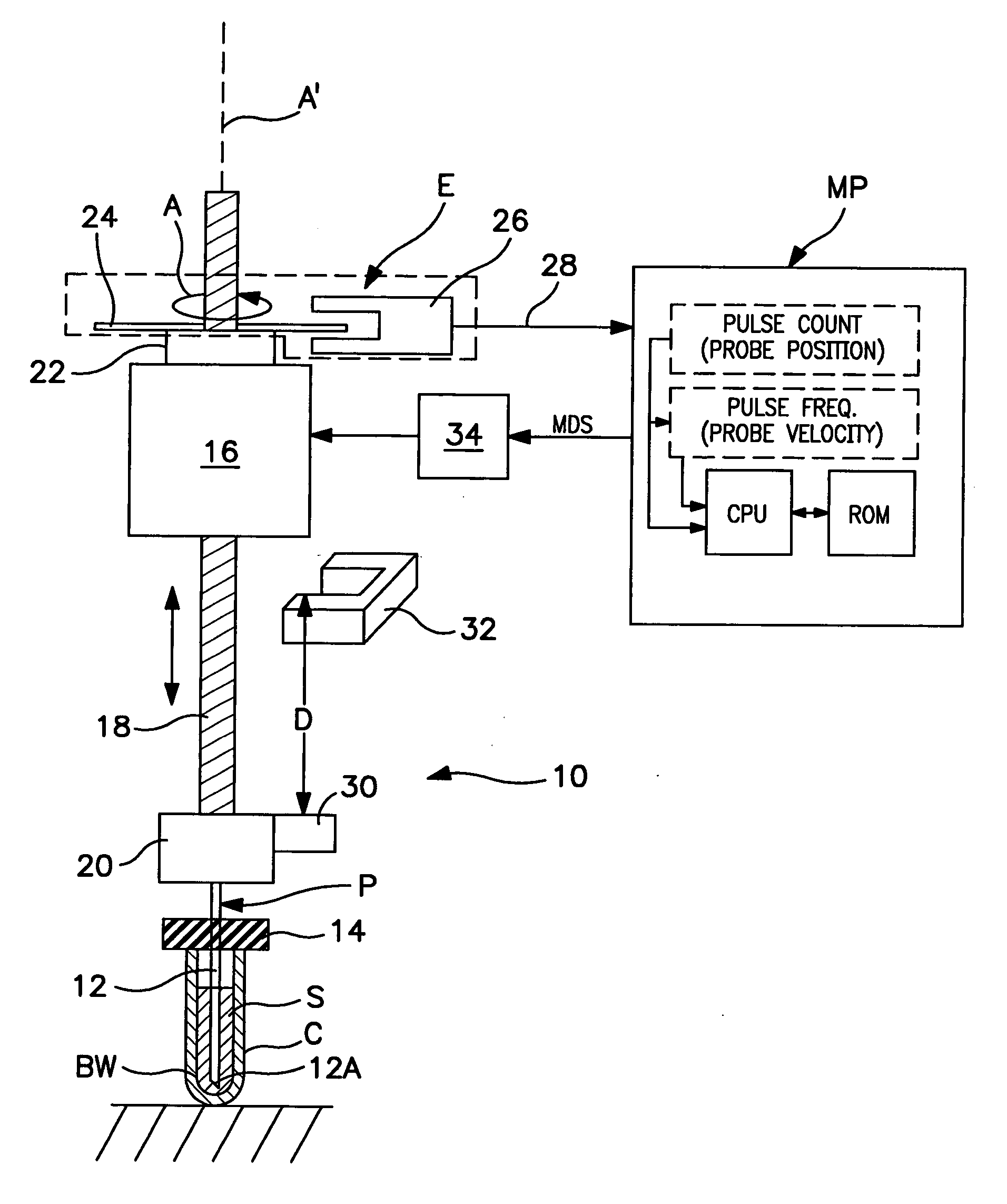
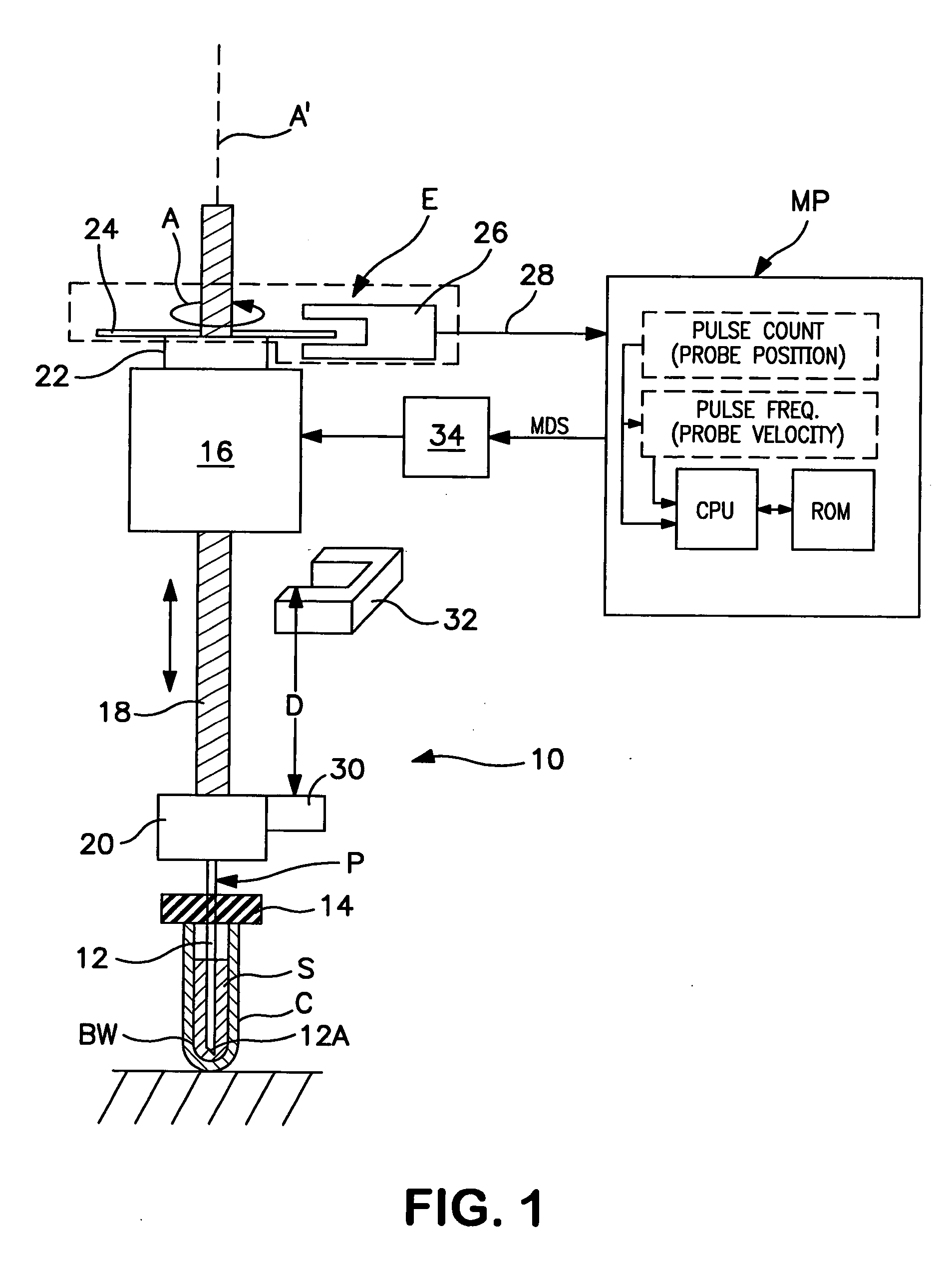
[0014] Referring now to the drawings, FIG. 1 schematically illustrates a liquid-aspiration apparatus 10 embodying a preferred form of the invention. Apparatus 10 generally comprises a vertically-movable aspiration probe P that is selectively operable to extract a predetermined volume of a liquid sample S contained by a test tube or other container C, and to convey such sample volume towards a utilization device (not shown), e.g., a blood analyzer. The aspiration probe typically comprises a hollow cannula 12 having a sharpened distal end 12A. In a well-known manner, the aspiration probe is operatively connected to the suction end of a vacuum pump (not shown) that serves to selectively create a negative pressure (vacuum) within the cannula in order to aspirate sample liquid into the cannula and into the liquid conduit(s) to which it is fluidly connected. The sharpened distal end of the probe is adapted to puncture a rubber seal 14 positioned atop the sample container and to enter the ...


PUM

PropertyMeasurementUnit
timeaaaaaaaaaa
volumeaaaaaaaaaa
speedaaaaaaaaaa

Abstract

Apparatus and method for aspirating liquid from a container, e.g., a test tube or other vessel, includes apparatus for sensing that an aspiration probe tip is contacting the inside bottom wall of the container, whereby a maximum volume of liquid can be aspirated from the container. According to the invention, an encoder is mounted on the driven member of a motor (e.g., on a rotatably-driven drive shaft or a nut of a stepper or D.C. motor, or on a linearly-driven shaft of a linear actuator) used to rectilinearly advance the probe tip into the container. Such encoder produces a series of pulses indicating the speed and/or linear position of the probe tip. A motor controller responds to a predetermined change in pattern of pulses from the encoder indicating that movement of the probe tip has been resisted by the vessel bottom, whereby further movement of the driven member and of the probe connected thereto is arrested, and the probe tip remains in contact with the vessel bottom.

Description

BACKGROUND OF THE INVENTION [0001] 1. Field of the Invention [0002] The present invention relates to improvements in apparatus for aspirating liquids, e.g. biological specimens, from small vessels, e.g. test tubes or vials, for processing. More specifically, this invention relates to improvements in apparatus for sensing contact between the tip of a liquid-aspiration probe and the bottom of a vessel from which liquid is to be aspirated. The invention is particularly useful in automated hematology instruments for extracting the last useful blood sample volume from test tubes and the like for analysis. [0003] 2. The Prior Art [0004] In conducting tests on biological liquids, e.g., blood, it is common to employ automated instruments to extract liquid specimens from small vessels, such as test tubes and the like. Such instruments typically include a movably-mounted sample aspiration probe that is adapted to be driven downwardly into the interior of a vertically-oriented test tube to a p...

Claims


Application Information

Patent Timeline
Patent Type & Authority Applications(United States)
IPC IPC(8): G01N1/22
CPCG01N35/1016Y10T436/2575G01N2035/1025
Inventor LI, WILLIAM W.ZULETA, MARCOLARREA, PABLOGALVEZ, SANTIAGO
Owner BECKMAN COULTER INC
Why Eureka
Try Eureka