Novel lighting apparatus for navigational aids

a navigational aid and light-emitting diode technology, applied in lighting applications, landing aids, instruments, etc., can solve the problems of significant challenge in regard to led beam control, low brightness of led lights, and single led chip brightness still not matching that of conventional incandescent or arc lamps, etc., to achieve rapid deployment and reconfigurability, high output intensity

Active Publication Date: 2007-01-18
BWTEK LIGHTING
View PDF48 Cites 70 Cited by
  • Summary
  • Abstract
  • Description
  • Claims
  • Application Information

AI Technical Summary

Benefits of technology

[0014] A modular designed light emitting diode (LED) lighting apparatus is provided with high output intensity and precisely controlled beam property for navigational aids. The lighting apparatus includes a plurality of high intensity LED units adapted to produce a plurality of light beams, and a plurality of optical beam transformers, with each transformer positioned in a path of a beam among the plurality of light beams for individually controlling a set of properties of each beam and producing a transformed light beam with both the plurality of high intensity LED units and optical beam transformers disposed in a pre-calculated manner within the lighting apparatus. Thereby the transformed light beams are mixed to produce a desired illumination pattern. The apparatus further includes a micro-controller that is controllably coupled to the plurality of high intensity LED units. The micro-controller is adapted to receive instructions either local or remote to the apparatus for controlling a set of controllable parameters, and to process locally available information. The apparatus still further includes a direct current (DC) power supply electrically coupled to the plurality of high intensity LED units and the micro-controller for providing power thereto.
[0015] A method for producing a modular designed, quickly deployable and reconfigurable light emitting diode (LED) lighting apparatus for navigational aids is provided. The method includes: providing a plurality of high intensity LED units adapted to produce a plurality of light beams, and providing a plurality of optical beam transformers, each transformer being positioned in a path of a beam among the plurality of light beams, for individually controlling a set of properties of each beam and producing a transformed light beam with both the plurality of high intensity LED units and optical beam transformers disposed in a pre-calculated manner within the lighting apparatus, thereby mixing the transformed light beams to produce a desired illumination pattern. The method further includes providing a micro-controller controllably coupled to the plurality of high intensity LED units, the micro-controller being adapted to receive instructions either local or remote to the apparatus for controlling a set of controllable parameters, and process locally available information. The method still further includes providing a direct current (DC) power supply electrically coupled to the plurality of high intensity LED units and the micro-controller for providing power thereto, and assembling the above provided elements in a predetermined manner.

Problems solved by technology

One problem facing the LED lighting apparatus is the relatively low brightness of the LED lights.
Even with the recent development of LED technology, the brightness of a single LED chip still cannot match that of conventional incandescent or arc lamps.
This places a significant challenge in regard to LED beam control because the LED array cannot be viewed as a point light source.
In the above cited patents or patent applications, the light beam produced by the whole LED array is controlled by specially designed lenses or beam transformers, which are both complicated in structure and difficult to manufacture.
More importantly, these specially designed lenses or beam transformers limit standardization and mass production, which are the two key factors in driving down the cost of a lighting apparatus.
None of the above cited patents or patent applications address these issues.

Method used


Image

  • Novel lighting apparatus for navigational aids
  • Novel lighting apparatus for navigational aids
  • Novel lighting apparatus for navigational aids

Examples


Embodiment Construction

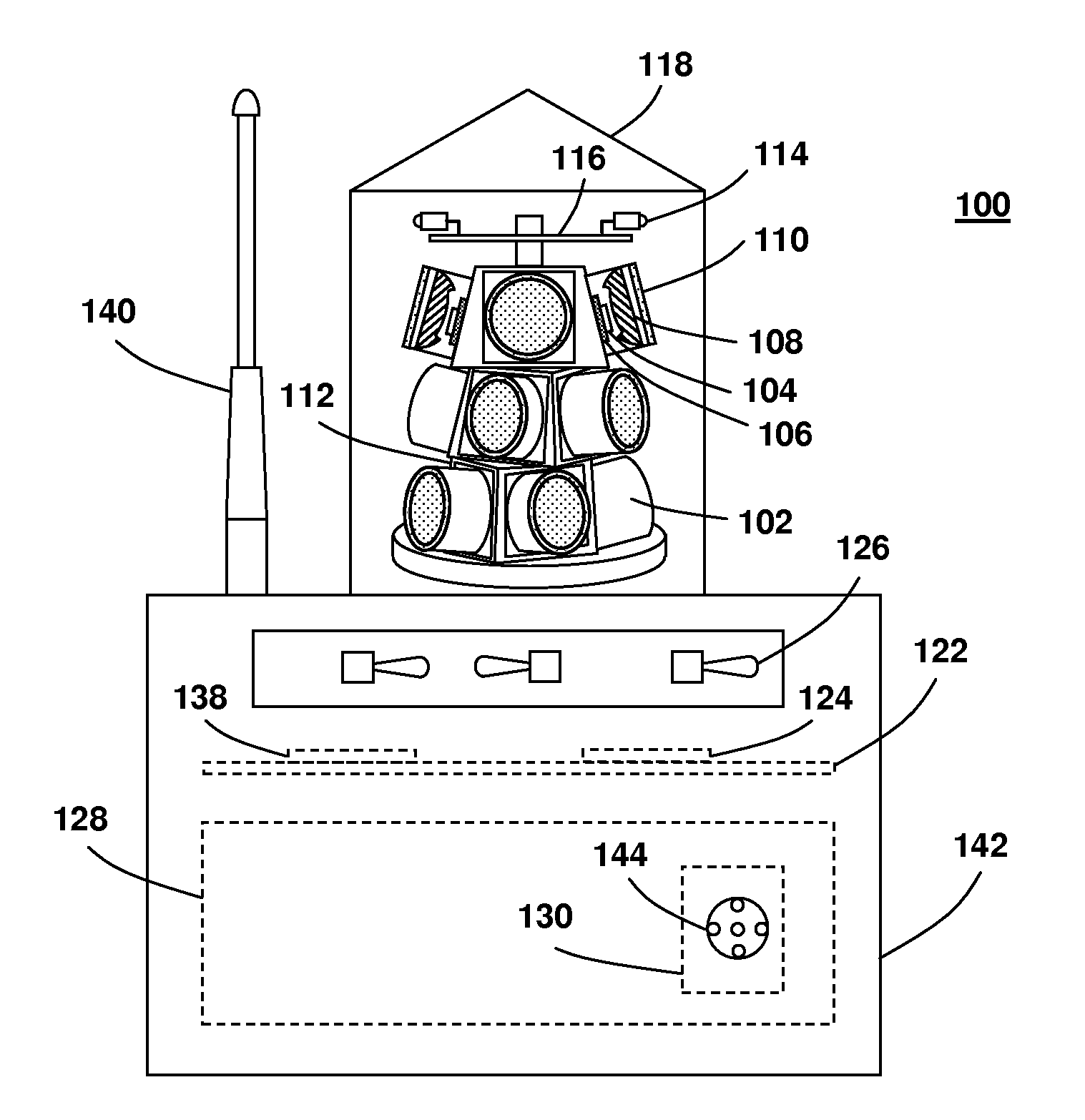
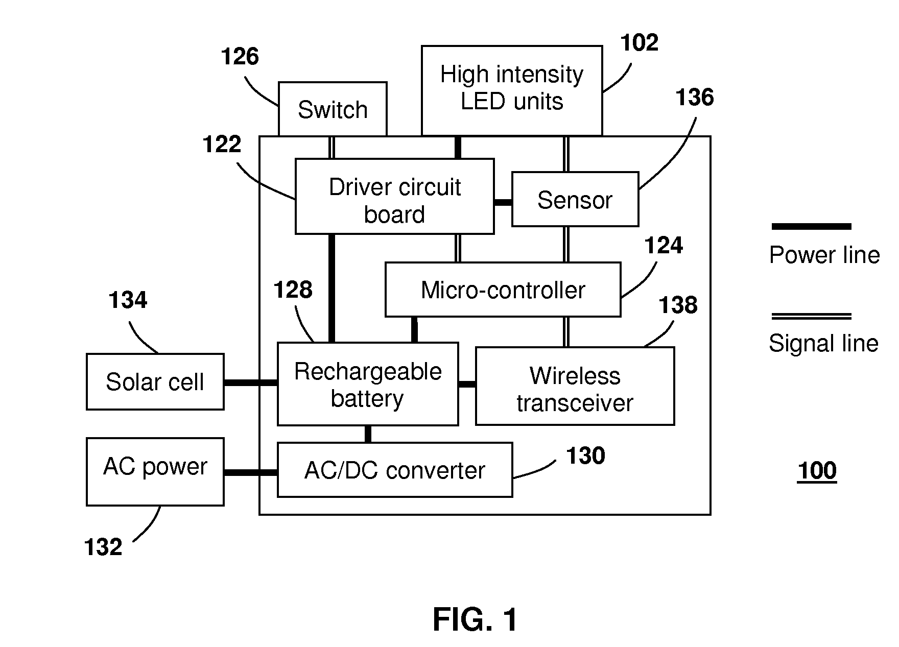
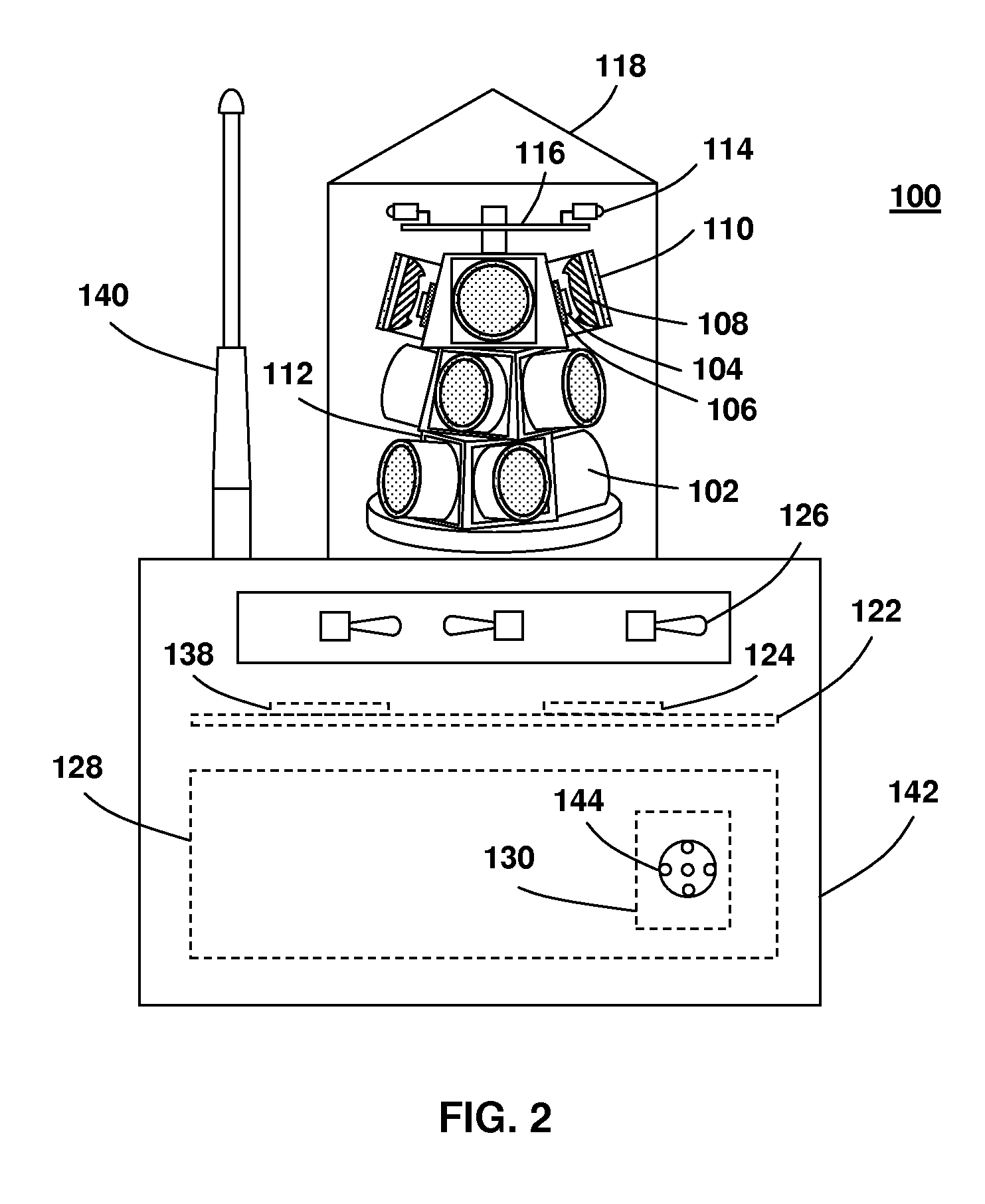
[0023] Before describing in detail embodiments that are in accordance with the present invention, it should be observed that the embodiments reside primarily in combinations of method steps and apparatus components related to an LED lighting apparatus for navigational aids. Accordingly, the apparatus components and method steps have been represented where appropriate by conventional symbols in the drawings, showing only those specific details that are pertinent to understanding the embodiments of the present invention so as not to obscure the disclosure with details that will be readily apparent to those of ordinary skill in the art having the benefit of the description herein.

[0024] In this document, relational terms such as first and second, top and bottom, and the like may be used solely to distinguish one entity or action from another entity or action without necessarily requiring or implying any actual such relationship or order between such entities or actions. The terms “com...


PUM


Abstract

A quickly deployable and reconfigurable light emitting diode (LED) lighting apparatus with high output intensity and precisely controlled beam property is disclosed for navigational aids. The lighting apparatus comprises an array of high intensity LED units with their light beams individually controlled by secondary optical systems. The transformed light beams mix in a pre-determined manner to produce an illumination pattern with desired intensity distribution. The LED lighting apparatus may further comprise a micro-controller, a plurality of sensor elements, and a wireless transceiver for remote monitoring and control. The lighting apparatus can be powered by rechargeable batteries for temporary or semi-permanent lighting. It can also be powered by standard power lines for permanent lighting.

Description

REFERENCE TO RELATED APPLICATIONS [0001] This application claims an invention which was disclosed in Provisional Patent Applications No. 60 / 595,566, filed Jul. 15, 2005, entitled “Portable Airfield Lighting System” and No. 60 / 767,489, file Apr. 11, 2006, entitled “Infrared LED Lighting Apparatus for Night Vision Based Navigation”. The benefit under 35 USC §119(e) of the above mentioned two U.S. Provisional Applications is hereby claimed, and the aforementioned applications are hereby incorporated herein by reference.FIELD OF THE INVENTION [0002] The present invention relates generally to a lighting apparatus and more specifically to a light emitting diode based lighting apparatus for navigational aids. BACKGROUND [0003] Lighting systems are important navigational aids for aircrafts, boats, or other vehicles, in providing guidance, signaling, and demarcation functions therefore. Semiconductor light emitting devices such as light emitting diodes (LEDs) have been identified to be the r...

Claims


Application Information

Patent Timeline
Patent Type & Authority Applications(United States)
IPC IPC(8): G08B21/00
CPCB63B51/00B63B2201/08B64C2027/8236B64F1/20F21W2111/06H05B37/0272G08B13/18H05B33/0803H05B33/0809H05B33/0842H05B37/00F21Y2101/02Y10S362/80F21Y2115/10H05B47/19H05B47/105H05B45/00H05B45/30
Inventor WANG, SEAN XIAOLUTIAN, RONGSHENG
Owner BWTEK LIGHTING
Why Eureka
Try Eureka