

Coordinate detecting device
a detection device and detecting device technology, applied in the field of coordinate detection devices, can solve the problems of distorted electric potential distribution of transparent resistance films, difficulty in small size of conventional coordinate detection devices, etc., and achieve the effect of increasing the detection accuracy of coordinate positions
- Summary
- Abstract
- Description
- Claims
- Application Information
AI Technical Summary
Benefits of technology
Problems solved by technology
Method used
Image

Examples
first embodiment
[0055] [Structure of Coordinate Detecting Device]
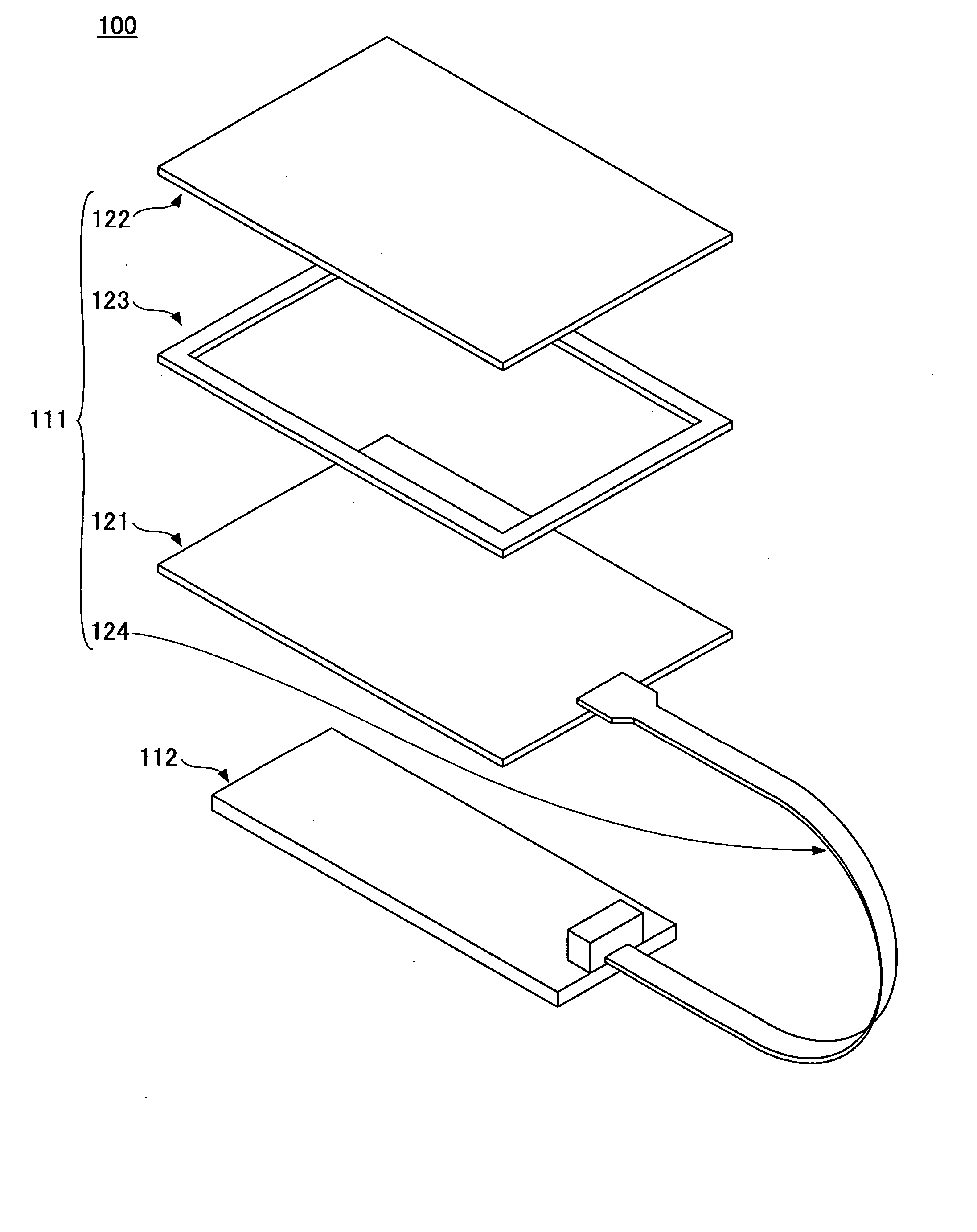
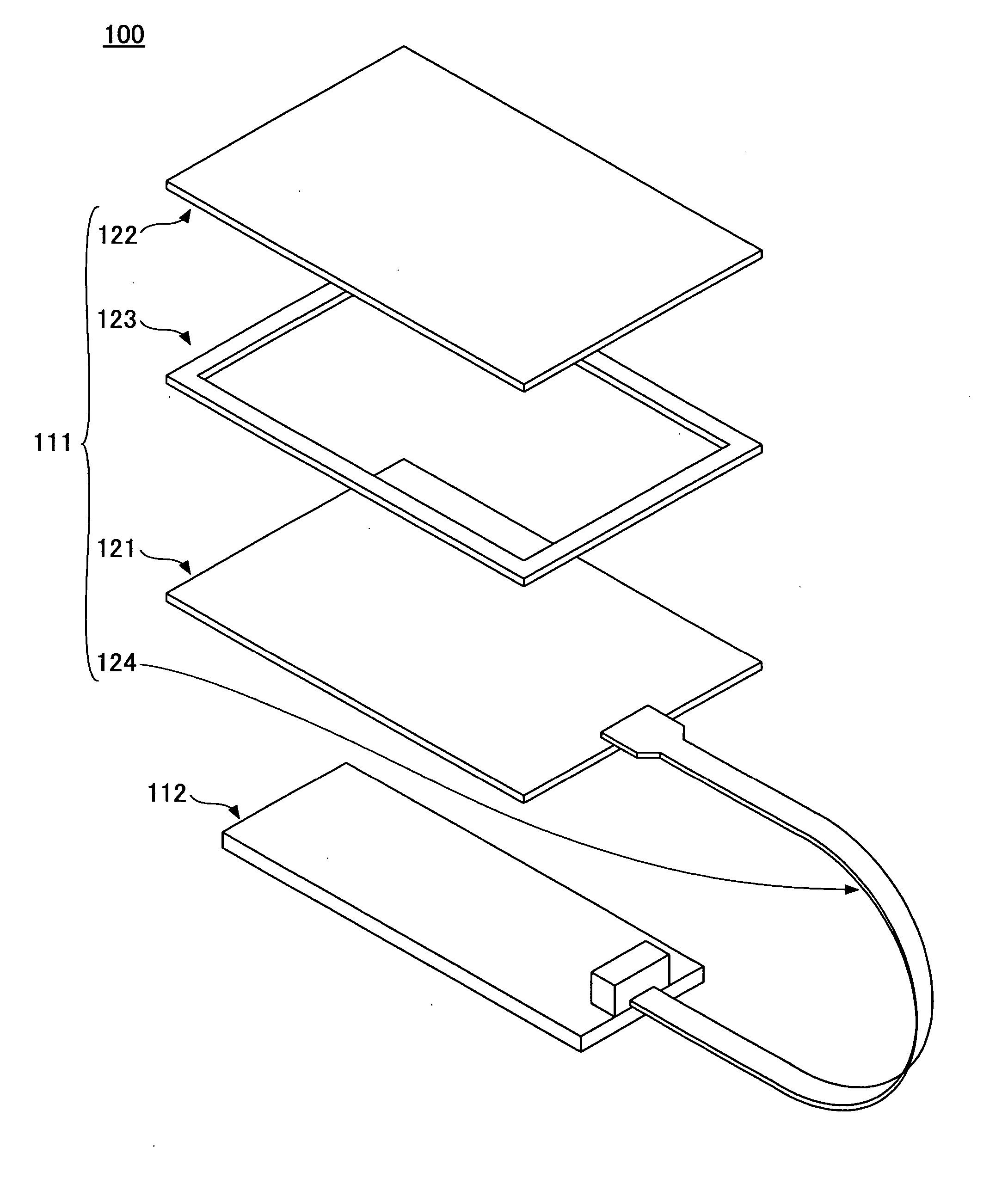
[0056]FIG. 1 is an exploded perspective view of a coordinate detecting device according to a first embodiment of the present invention.
[0057] In the first embodiment, as a coordinate detecting device 100, a five-line type analog resistance film touch panel is used. The coordinate detecting device 100 includes a panel section 111 and an interface board 112.
[0058] The panel section 111 includes a lower substrate 121, an upper substrate 122, a spacer 123, and an FPC (flexible print cable) 124. In the exemplary embodiment, the lower substrate 121 is bonded to the upper substrate 122 via the spacer 123. The spacer 123 is an insulating double sided adhesive tape and bonds the lower substrate 121 to the upper substrate 122 to provide a predetermined space between the lower substrate 121 and the upper substrate 122 at a part other than the spacer 123. The FPC 124 has a structure in which first wiring through fifth wiring (not shown) are for...
PUM
 Abstract
Description
Claims
Application Information