Direct type backlight module

Active Publication Date: 2007-01-18
AU OPTRONICS CORP
View PDF10 Cites 6 Cited by
  • Summary
  • Abstract
  • Description
  • Claims
  • Application Information

AI Technical Summary

Benefits of technology

[0008] The object of the present invention is to provide a direct type backlight module comprising a heat-insulating element which may increase the light emitting efficiency of the backlight module.

Problems solved by technology

The accumulation of heat may influence both the light source and electrical elements simultaneously, and may thus further affect the efficiency of the light source and the heat resistance of the electrical elements.
Empirically, the heat may decrease the light emitting efficiency of the backlight module by about 10%.
Hence, how to reduce the effect of the generated heat upon the light emitting efficiency is definite an important issue in this industry.

Method used


Image

  • Direct type backlight module
  • Direct type backlight module
  • Direct type backlight module

Examples


Embodiment Construction

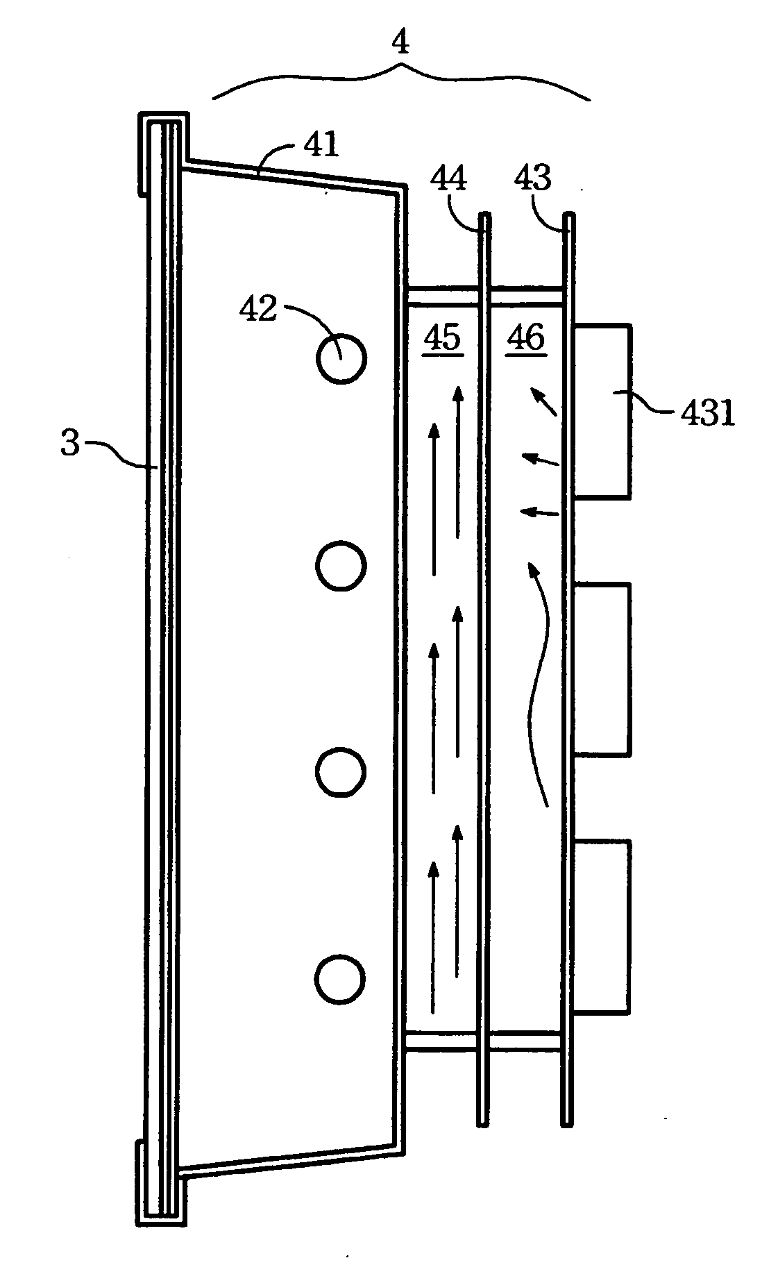
[0017] The present invention relates to a direct type backlight module, by adding a heat insulating element therein to enhance the total light emitting efficiency of the direct type backlight module. What follows is an embodiment to interpret the present invention detail, but not try to restrict the scope of the present invention.

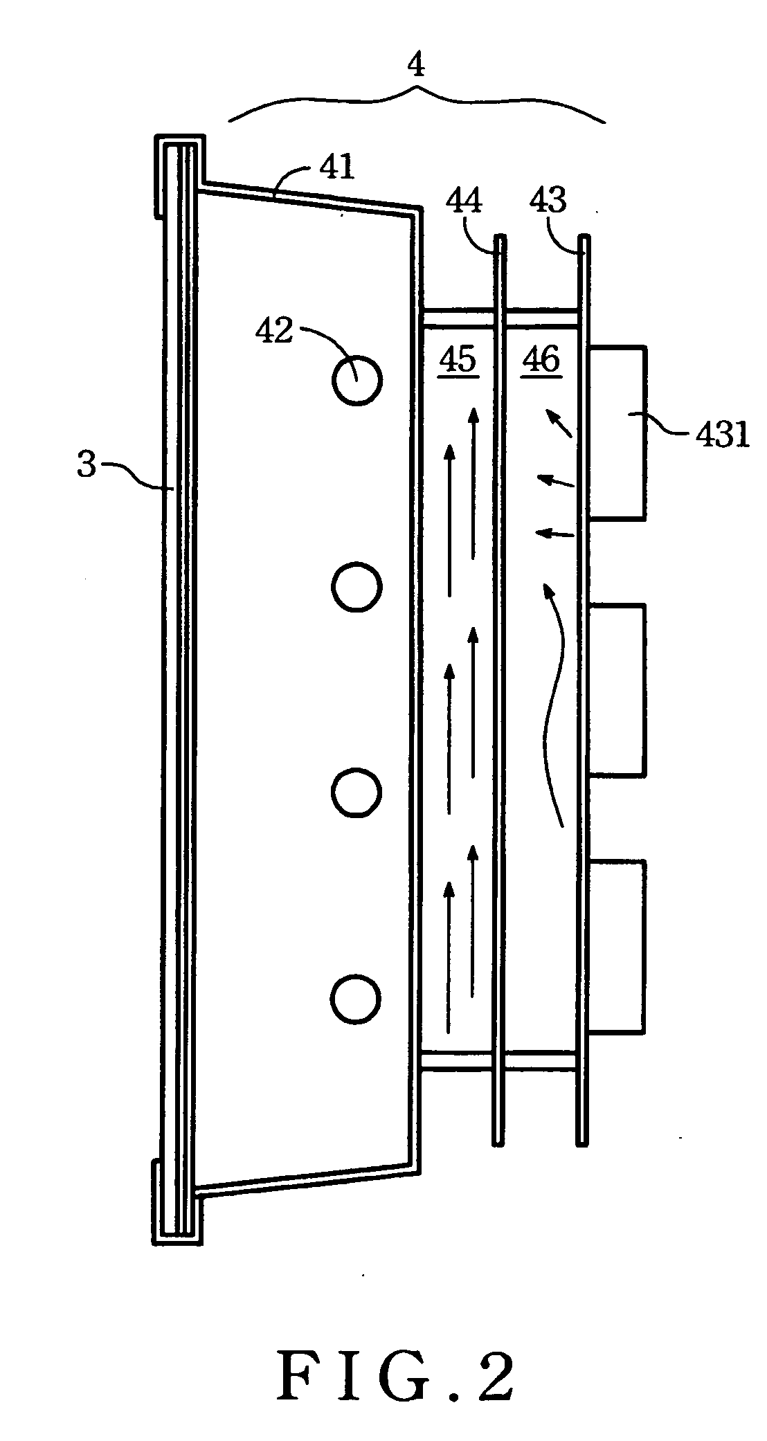
[0018] Please refer to FIG. 2, which shows an LCD panel 3 and one embodiment of the direct type backlight module 4 in accordance with the present invention. The direct type backlight module 4 comprises a back bezel 41, a light source 42, a circuit board 43, and a heat insulating element 44. The light source 42 is disposed within the back bezel 41. The circuit board 43 is disposed outside the back bezel 41. The circuit board 43 further comprises a plurality of driving elements 431, which are all electrically connected to the light source 42. As shown, the heat-insulating element 44 is disposed between the back bezel 41 and the circuit board 43 so as to form...


PUM


Abstract

A direct type backlight module comprises a back bezel, a light source, a circuit board, and a heat-insulating element. The light source comprising a plurality of driving elements coupled thereto is disposed within the back bezel. The circuit board is disposed outside the back bezel. The heat-insulating element is disposed between the back bezel and the circuit board so as to form a first convectional space and a second convectional space.

Description

BACKGROUND OF THE INVENTION [0001] (1) Field of the Invention [0002] The present invention relates to a direct type backlight module, especially for a backlight module that comprises a heat-insulating element for enhancing light emitting efficiency of the backlight module. [0003] (2) Description of the Prior Art [0004] The advantages of high pixels, low irradiation, high space flexibility, and low power consumption make the Liquid crystal displays (LCD) more and more popular in the display markets. In the LCD, the liquid crystal molecules can not luminescence themselves, and so a backlight light module is needed to provide light sources of the display. [0005] Please refer to FIG. 1A, which shows a cross section view of a conventional liquid crystal panel 1 and a direct type backlight module 2 as the light source of the panel 1. The backlight module 2 comprises a back bezel 21, a light source 22, and a plurality of driving elements 23. The driving elements 23 comprise some electrical...

Claims


Application Information

Patent Timeline
IPC IPC(8): G02F1/1333
CPCG02F1/133608G02F2201/36G02F2001/133314G02F1/133314
Inventor TSAI, YI-SHIUANWANG, YI-JING
Owner AU OPTRONICS CORP
Why Eureka
Try Eureka